This thread has been locked.

If you have a related question, please click the "Ask a related question" button in the top right corner. The newly created question will be automatically linked to this question.

IWR6843ISK: DCA1000 board Hardware In Loop (HIL) / DMM

Part Number: IWR6843ISK

Hi there,

Could I please get some assistance about Hardware In Loop (HIL) on TI’s ECA1000 board? The progress currently is that test data from FPGA can be sucessfully written into PING buffer at 0x5200_0000 on MSS core and interrupts can also be captured on DSP side. However, one problem that turns out is that data in PING buffer and data in PONG buffer do not show up at the same time. Please see the below testing process in details:

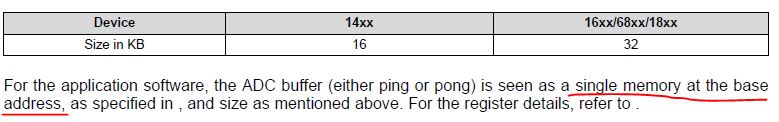
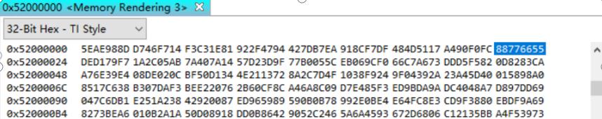
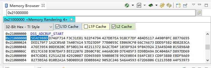
After initialization of DMM1 and DMM2 on DSP side, some randam data can be seen from starting address 0x5200_0000 (32K) and these data do not change until powering off.

Following https://e2e.ti.com/support/sensors/f/1023/t/861828#pi320995=2

The sequence we tried:

1) set to PING buffer address 0x0042_0000

2) frame start interrupt

3) write data into PING buffer

4) switch to PONG buffer 0x0063_0000

5) PING PONG interrupt

6) some delay

7) write data into PONG buffer

8) switch back to PING buffer

9) PING PONG interrupt

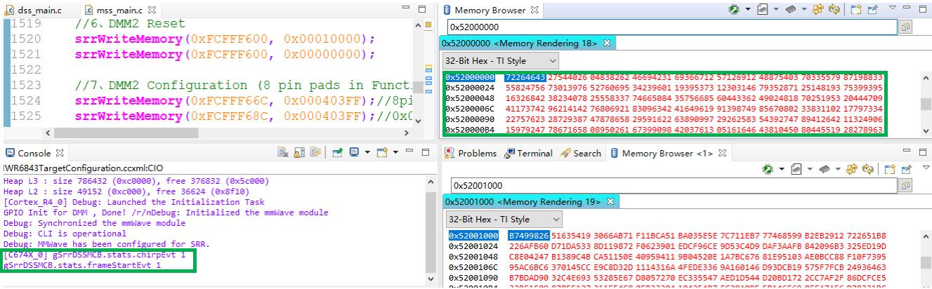
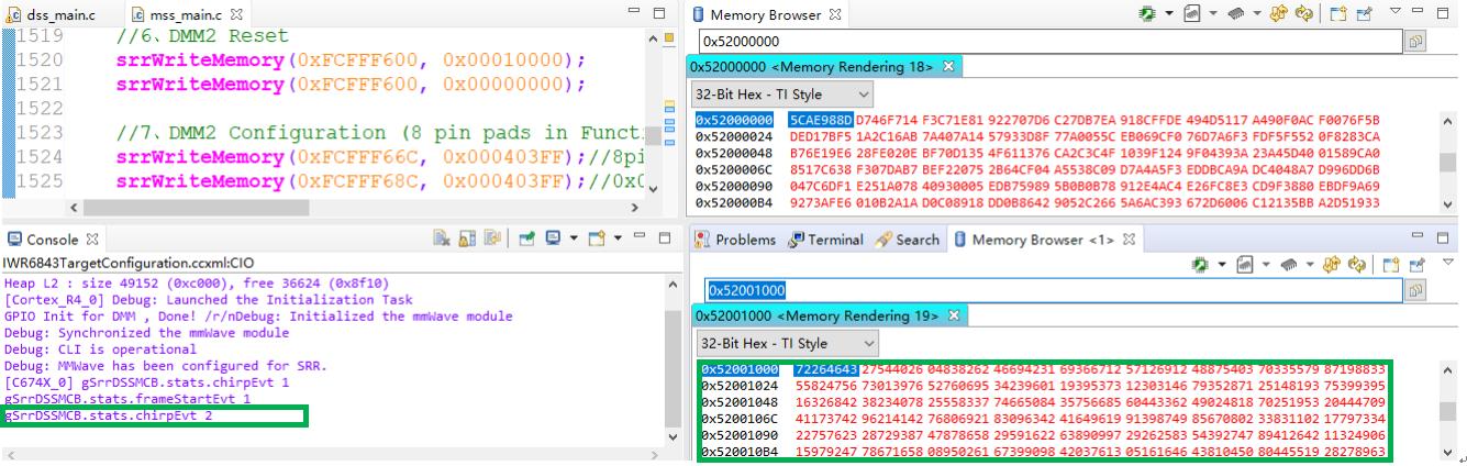
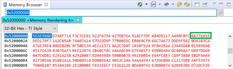
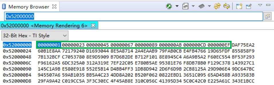
The first screen shot above gives the result of PONG buffer data change only. One interesting thing found is that the PING buffer data will actually appear after disconnecting and hardware reset. See the 2nd screen shot. Moreover, after debugging, we did capture one frame interrupt and two chirp available interrupts.

So far, our guess is that the random data which shows up at the beginning seems to be the problem. There is data from 0x5200_0000 to 0x5200_7FFF, while other address locations are ?????? (no data). These data might have higher priority which blocks us from seeing PING or PONG data at the same time.

We also tried to use copy memory command while chirp available interrupt counter reaches 1 in order to transfer PING data to other address, but it does not work.

Thanks,

  • To make things more clear, we added more delay time after ping-pong interrupt and used a seperate window for monitoring the change.

    After PING (4K bytes) and ping-pong interrupt, the mss core can see the data change at ping buffer from 0x5200_0000 to 0x5200_1000 as well as one frame interrupt and one chirp available interrupt.

    Then after writing to PONG and sending the interrupt, the MSS core can also see the data change at pong buffer from 0x5200_1000 to 0x5200_2000 as well as the 2nd chirp available interrupt.

    Clearly, after writing to PONG, the previous data written to PING buffer are lost; however, these data will be visiable again the next time after writing to PING. So, you can only see PING data or Pong data at a time, and this gives us a hard time to read the data out. Any ideas?

    Thanks,

  • Hello

    Please  help us  understand which documentation and resource have you been  following to implement this.

    Thank you,

    Vaibhav

  • We are following "Hardware in loop for the data play back from the DMM interface" and "DMM_Configuration_psudo_code_rev2" given by the previous post  

    https://e2e.ti.com/support/sensors/f/1023/t/861828#pi320995=2

  • Miaoshu,

    I found below in TRM.

    Miaoshu Wangxu1 said:
    Then after writing to PONG and sending the interrupt, the MSS core can also see the data change at pong buffer from 0x5200_1000 to 0x5200_2000 as well as the 2nd chirp available interrupt.

    As above info, ping/pong buffer has the same base address 0x52000000 (mss map). As one time, you can only see one of ping/pong buffer which is not using to get adc data from DFE/test pattern or DMM.