This thread has been locked.
If you have a related question, please click the "Ask a related question" button in the top right corner. The newly created question will be automatically linked to this question.
Hello officers,
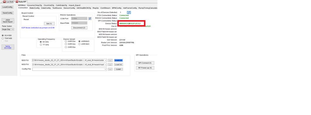
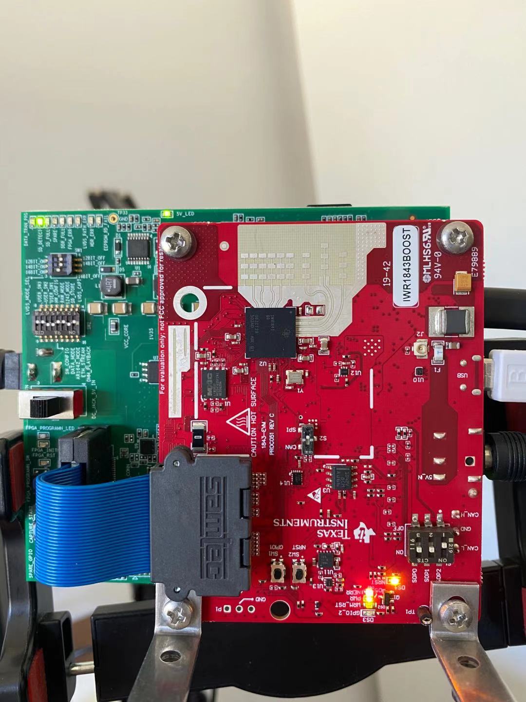
"MSS Power Up async event was not received!" problem happened in SPI connecting stage. I have searched this problem on forum, and I have already given the erase command to board through Uniflash, but it still dosen't work. I also checked SOP to mode 2 and put switch 2 to SPI mode. Beside, I have checked that 6 ports are listed in device manager properly.
I use mmWave Studio 2.1.0.0
There is my output:
GM: Constructor
GM: Sat Jan 23 12:21:18 2021
RSTD.Transmit("/Settings")
[12:21:18]
[12:21:18] ### Running Startup script: "C:\ti\mmwave_studio_02_01_00_00\mmWaveStudio\Scripts\Startup.lua" ###
[12:21:18] RSTD.SetAndTransmit ("/Settings/Scripter/Display DateTime" , "1")
[12:21:18] RSTD.SetAndTransmit ("/Settings/Scripter/DateTime Format" , "HH:mm:ss")
[12:21:18] Scripter ignored: Attempt to UnBuild() again or before Build.
[12:21:18] RSTD.SetVar ("/Settings/Clients/Client 0/Dll" , "C:\\ti\\mmwave_studio_02_01_00_00\\mmWaveStudio\\Clients\\\\LabClient.dll")
[12:21:18] RSTD.SetVar ("/Settings/Clients/Client 0/Use" , "TRUE")
[12:21:18] RSTD.SetVar ("/Settings/Clients/Client 1/Use" , "FALSE")
[12:21:18] RSTD.SetVar ("/Settings/Clients/Client 2/Use" , "FALSE")
[12:21:18] RSTD.SetVar ("/Settings/Clients/Client 3/Use" , "FALSE")
[12:21:18] RSTD.SetVar ("/Settings/Clients/Client 4/Use" , "FALSE")
[12:21:18] RSTD.SetVar ("/Settings/AL Client/AL Dll" , "C:\\ti\\mmwave_studio_02_01_00_00\\mmWaveStudio\\RunTime\\SAL.dll")
[12:21:18] RSTD.SetVar ("/Settings/Clients/Client 0/GuiDll" , "")
[12:21:18] RSTD.SetVar ("/Settings/AutoUpdate/Enabled" , "TRUE")
[12:21:18] RSTD.SetVar ("/Settings/AutoUpdate/Interval" , "1")
[12:21:18] RSTD.SetVar ("/Settings/Monitors/UpdateDisplay" , "TRUE")
[12:21:18] RSTD.SetVar ("/Settings/Monitors/OneClickStart" , "TRUE")
[12:21:18] RSTD.SetVar ("/Settings/Automation/Automation Mode" , "false")
[12:21:18] RSTD.Transmit("/")
[12:21:18] RSTD.SaveSettings(): Settings saved to "C:\Users\Zber\AppData\Roaming\RSTD\config.xml"
[12:21:18] RSTD.Build()
[12:21:18] RSTD.SaveSettings(): Settings saved to "C:\Users\Zber\AppData\Roaming\RSTD\config.xml"
[12:21:18] RSTD.Transmit("/")
[12:21:18] RSTD.AL_Build()
[12:21:18] RSTD.AL_LoadXml()
[12:21:18] RSTD.Transmit("/")
[12:21:18] RSTD.AL_Init()
[12:21:18] RSTD.Clients_Build()
[12:21:18] GM: Init
[12:21:18] GM: Loaded 'C:\ti\mmwave_studio_02_01_00_00\mmWaveStudio\Clients\\LabClient.dll'
[12:21:18] GM: 1 Guest (s) init
[12:21:18] GM: 1 Module(s) init
[12:21:18] GM: 2 Tab (s) init
[12:21:18] RSTD.Client_LoadXml()
[12:21:18] [RadarAPI]: ar1.selectRadarMode(0)
[12:21:18] [RadarAPI]: Status: Passed
[12:21:18] Matlab Runtime Engine is installed
[12:21:18] [RadarAPI]: Starting Matlab Engine..
[12:21:20] [RadarAPI]: Matlab Engine Started!
[12:21:22] [RadarAPI]: ar1.selectCascadeMode(0)
[12:21:22] [RadarAPI]: Status: Passed
[12:21:22] [RadarAPI]: ar1.LoadSettings('C:\Users\Zber\AppData\Roaming\RSTD\ar1gui.ini')
[12:21:22] TESTING = false
[12:21:22] RstdNet: Port 2777: Listening..
[12:21:22]
[12:21:22] ***Script completed successfully.***
[12:21:24] [RadarAPI]: Opening Gpio Control Port()
[12:21:24] [RadarAPI]: Status: Passed
[12:21:25] [RadarAPI]: Opening Board Control Port()
[12:21:25] [RadarAPI]: Status: Passed
[12:21:26] [RadarAPI]: ar1.FullReset()
[12:21:26] [RadarAPI]: Status: Passed
[12:21:27] [RadarAPI]: Closing Board Control Port()
[12:21:27] [RadarAPI]: Status: Passed
[12:21:27] [RadarAPI]: Closing Gpio Control Port()
[12:21:27] [RadarAPI]: Status: Passed
[12:21:27] [RadarAPI]: ar1.SOPControl(2)
[12:21:27] [RadarAPI]: Status: Passed
[12:21:28] [RadarAPI]: ar1.Connect(3,115200,1000)
[12:21:29] [RadarAPI]: ar1.Calling_IsConnected()
[12:21:30] [RadarAPI]: ar1.SelectChipVersion("AR1642")
[12:21:30] [RadarAPI]: Status: Passed
[12:21:30] [RadarAPI]: ar1.SelectChipVersion("AR1642")
[12:21:30] [RadarAPI]: Status: Passed
[12:21:30] [RadarAPI]: ar1.deviceVariantSelection("XWR1843")
[12:21:30] [RadarAPI]: Status: Passed
[12:21:30] [RadarAPI]: ar1.frequencyBandSelection("77G")
[12:21:30] [RadarAPI]: ar1.SelectChipVersion("XWR1843")
[12:21:30] [RadarAPI]: Status: Passed
[12:21:30] Device Status : XWR1843/QM/SOP:2/ES:2
[12:21:30] [RadarAPI]: ar1.SaveSettings('C:\Users\Zber\AppData\Roaming\RSTD\ar1gui.ini')
[12:21:33] [RadarAPI]: ar1.DownloadBSSFw("C:\\ti\\mmwave_studio_02_01_00_00\\rf_eval_firmware\\radarss\\xwr18xx_radarss.bin")
[12:21:34] [RadarAPI]: Downloading BSS Patch RPRC Binary..
[12:21:41] [RadarAPI]: ar1.GetBSSFwVersion()
[12:21:41] [RadarAPI]: BSSFwVersion:(02.00.00.01 (05/10/17))
[12:21:42] [RadarAPI]: ar1.GetBSSPatchFwVersion()
[12:21:42] [RadarAPI]: BSSPatchFwVersion:(01.02.05.02 (30/04/19))
[12:21:42] [RadarAPI]: ar1.DownloadMSSFw("C:\\ti\\mmwave_studio_02_01_00_00\\rf_eval_firmware\\masterss\\xwr18xx_masterss.bin")
[12:21:43] [RadarAPI]: Downloading MSS RPRC Binary..
[12:21:54] [RadarAPI]: ar1.GetMSSFwVersion()
[12:21:54] [RadarAPI]: MSSFwVersion:(01.02.05.02 (16/07/19))
[12:22:28] [RadarAPI]: ar1.PowerOn(0, 1000, 0, 0)
[12:22:28] Status: Failed, Error Type: RESP TIMEOUT
[12:22:32] MSS Power Up async event was not received!
1. all 6 ports can be seen in the device manager
2. I can see the packages Ethernet
There are my device snapshot and mmWave studio screenshot
Could u help me solve this problem?
Kind regards,
Xi
Hello Officers,
Is the MSS Path Firmware ver: NA in the mmWave studio connection section after clicking the "Load MSS FW" botton means something.
I actullay checked the training vedio of DCA 1000 EVM again and it shows same in the video.
Xi
Hi, Xi:
Please check this DCA1000 debug notebook located at:
[FAQ] DCA1000EVM: DCA1000EVM Debug Resources - Sensors forum - Sensors - TI E2E support forums
Please also help your device version and check with radar studio release notes to see whether it is supported.
Best,
Zigang
Hi, Zigang
I have checked DCA1000EVM bebug document and I found this issue "When using IWR1843, SPI Connect fails after loading the provided BSS and MSS firmware in mmWave Studio" is quite similar to what I met and the root cause is "The firmware version does not align with the silicon version". I get confused here as I do not know how to solve this issue. Do I need to change the MSS FW versino that I currently used or the BSS FW version in this case?
I also found this post which describe the procdure to capture the raw data for IWR1843BOOST in more detailed way.
IWR1843BOOST: mmwave Studio Data Capture Demo corruption - Sensors forum - Sensors - TI E2E support ...
I will follow this procedure to redo the setup again.
Is there any other point I need to notice?
Best
Xi
Early radar studio version support early version of the EVM board. IF you found the latest radar studio does not support your device version, you need to go back to earlier versions of radar studio.
1) You can find your device version when you click on "connect" in the radar studio, the right side shows the device name and version.
2) To find the radar studio support device version, you can find the release information at https://software-dl.ti.com/ra-processors/esd/MMWAVE-STUDIO/latest/index_FDS.html. You can find the release notes for the previous version by click on the highlighted link below, and then find the previous of the previous version in the similar way.
Let me know if it helps. The problem in your referred e2e happens in the later stage of the data collection.
Best,
Zigang
Hi, Zigang
First of all, thanks for u reply.
I have checked each version of mmWave studio and I didn't find a compatible version with my device(IWR1843BOOST).
There are only 4 versions of mmWave Studio, including 2.01.01.0 , 2.01.0.0, 2.0.0.2 and 1.0.0.0. In their release notes, my device is't in the supported device list. In addition, my device(IWR1843BOOST) should be came out in second half year of 2020 so I think the earlier version should not be working in this way. I actually have tried each of these 4 versions and non-of-them was working.
Is that means I need to write my own code which capture the raw data from ethernet port.
Best,
Xi
Hi Zigang,
The problem is “The firmware version does not align with the silicon version“ and I cannot change the silicon verison. So I am thinking where I can find the newest verisoni of MSS firmware. I have tried to search in TI website but I didn't find one. I also searched in the SDK pacakge and I can only found BSS firmware not the MSS one.
Best,
Xi
HI, Xi:
I consult with the team. It turns out that the release notes has a typo, and it support XWR1843 ES2 instead of XWR1843 ES1.
IWR1843BOOST is just the board name, not the device name. Your device is XWR1843ES2 based on your second picture in your original thread.
Please try with the latest radar studio version 02.01.01.00. If it still does not work, please try to run SDK OOB demo with IWR1843BOOST by itself (without DCA1000) to make sure the device is working.
Best,
Zigang
Hi, Zigang:
I have tried the latest radar studio version but it still didn't work. The SDK OOB demo with IWR1843BOOST works well.
I first tried the OOB demo and I found that I cannot capture the ADC data by IWR1843BOOST only. Therefore, I went to the DCA1000 and mmWave studio.
The only concern from my side is that the power supply I currently use is 5V 2.4A which is less than the specified power (5V 2.5A). I am not sure that will cause SPI connection failure. I have ordered required power supply.
Best,
Xi
Hi, Xi:
Please check your power supply, it needs to be 3A, 5V. If it is the right type, try a new power supply.
Best,
Zigang
Hi, Zigang
The problem is still here. I tried both 5V 3A power supply and adjustable power supply but the problem is still same. Is there some problems with my operation system of my PC? I am currently use WIN10 64bite system.
Best,
Zigang
HI, Xi:
Sorry to hear that. I also have the same win10 64 bit system on my PC. I noticed that the SD_card LED light is on your DCA1000 board, can you take the SD-card off from the DCA1000 board and check the sw2 switch setting with the DCA1000 training video:
Although this usually matters during the data capture step.
Best,
Zigang
HI, Xi:
I am no idea now. Your board runs well with OOB demo and the setup looks all right to me. And you have tried different power supplies. Do you have other EVM board to try?
I tried on one of my older version of xwr6843EVM board, and it works fine for me.
Best,
Zigang
Hi Zigang,
I only have two package including DCA1000EVM and IWR1843BOOST. I have tried on both but none of them is working.
I actually borrowed another laptop from my friend and I am going to try setup on that laptop.
Best
Xi
Get a feedback within the team:
The S2 switch needs to be set to the “SPI” position. It appears that the switch is set in the mid-point position. This switch is used to toggle between the SPI and CAN connection being brought out on the EVM. The S2 switch needs to be set to the SPI position. The SPI protocol is what is used for issuing commands in mmWave Studio to the AWR1843BOOST EVM. This is why the SPI Connect step is erroring out every time, regardless of the firmware being loaded onto the device.
Please make this change, setting the S2 switch to the “SPI” position, and see if this resolves your issue.
Best,
Zigang
Hi, Zigang
I have checked S2 switch several times and it is in the position pointing to SPI mode. Despite this, I have tried to run it again but the problem is still the same.
The solution that the team point out is the one I have found in the other post.
And you can check the picture, the red box shows the position is on SPI.
Best,
Zigang
Can you cross check this following e2e (the last reply), IWR1843BOOST: mmwave studio RESP TIMEOUT during SPI connection - Sensors forum - Sensors - TI E2E support...
Best,
Zigang
Hi Zigang,
I can see that the post has the problem with S2 swich, but for mine I set to the correct position.
Is there anyway that I can contact you through the phone call as I really need you.
Best,
Xi
Hi Zigang,
Besides, I will purchase an another set of power supply that provide 5v, 4A power.
I hope it works well after I recevied them.
And also, I tried another windows laptop, the problem is still the same.
Best,
Xi
Hi, Xi:
Sorry right now, I do not have the newest version of the board right now, I am in the process of ordering it. I will consult with a team to help. Please give me some time.
Best,
Zigang
Hi Zigang,
I am very thankful for you continue support which means a lots for me.
If you send me you phone number and tell me what time to call you after you receviced the device. I think it would be really helpful for us to finish this annoying problem.
Best,
Xi
Here is the feedback I got:
QM means it is a IWR board not AWR. The firmware should be the same for both IWR and AWR boards.
Can you probe on a scope the SPI pins to check if there is any SPI activity?
Best,
Zigang
HI,
I got my IWR1843 board, and it works for me.
So please double check
1) your blue cable (that connect between two boards) are connected well.
2) your sw2 is switch to SPI, please double check with scope on SPI pins. It is possible that your SPI connection is not working well. In that case, please check another board if it is possible.
Best,
Zigang
Hi Zigang,
I don't have an oscilloscope device now. I actually double checked the 60pin cables and it is not problem.
Do you suggest me to purchase one in order to test the status of SPI pins.
Best,
Xi
Hi Zigang,
BTW, I could use the LVSD to collect the raw data. Therefore, I think that the only problem is located in the SPI connection. And I also purchase a new set of power supply which will be delivered in 3 days.
Best,
Xi
HI, Xi:
Sorry I can not make a decision for me. If Oscilloscope is not much user to you in general, maybe you can order a new board.
Best,
Zigang
Hi Zigang,
Good news, the new board is working for me. For the old board, all funcitons are working except the SPI connection which drives me crazy.
Finally, I found out the problem and thanks for your consistent support.
Best,
Xi