This thread has been locked.

If you have a related question, please click the "Ask a related question" button in the top right corner. The newly created question will be automatically linked to this question.

DRV421: Magnetic design for DRV421

Part Number: DRV421

Hello,

I'm trying to develop a current transducer using the DRV421, both for current measurement and for Residual current detection.

The specification are about 50A for maximum current and around 10 mA of residual current with an accuracy hoped around 1mA.

Our case is rectangular, and not toroidal, and probably I will be able to wind the compensation winding only on one leg.

Watching the EVM, I see that the ferrite has been milled both to obtain a gap and to insert the chip.

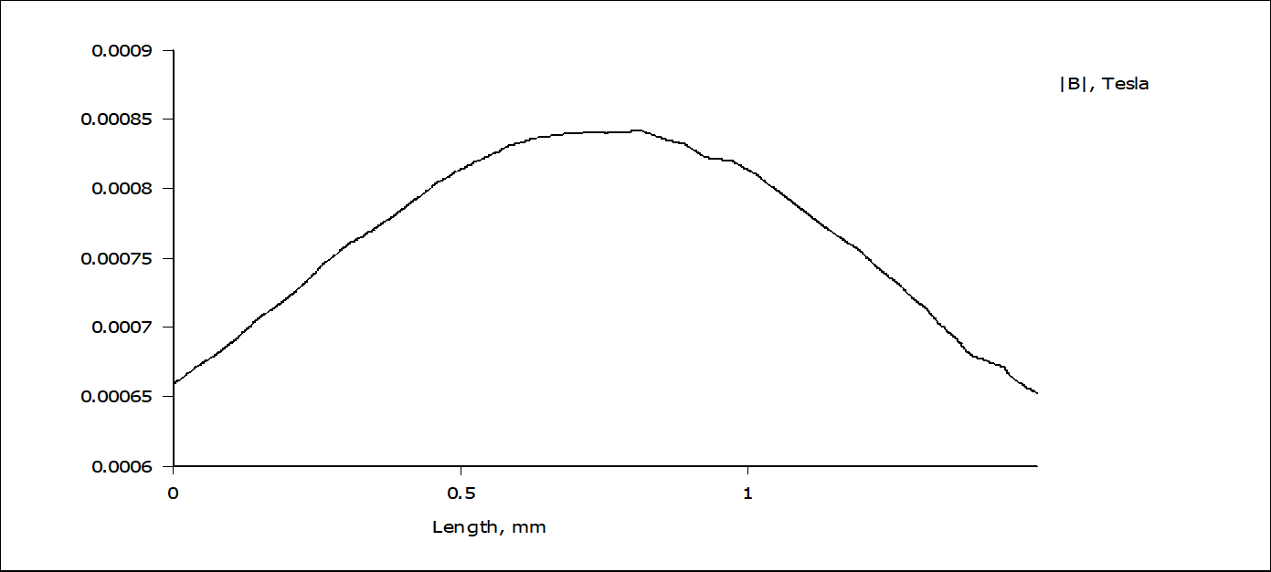
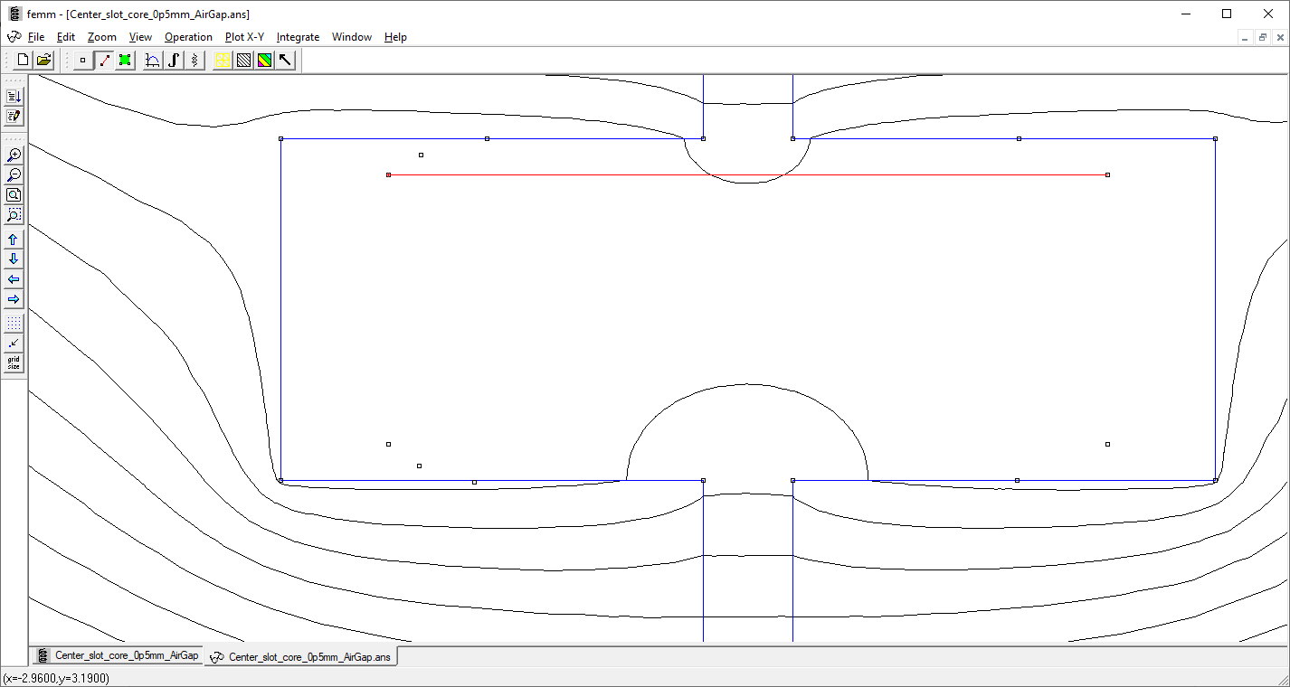
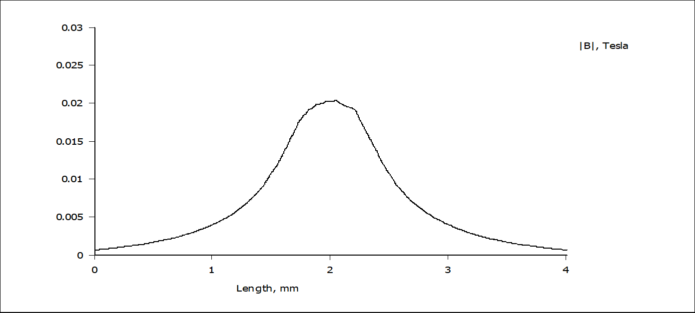
Why do you insert the chip longitudinally instead of orthogonally like other hall chip? Is the B-field inside the gap uniform even with two gaps that cross each other like the figure attached  ?
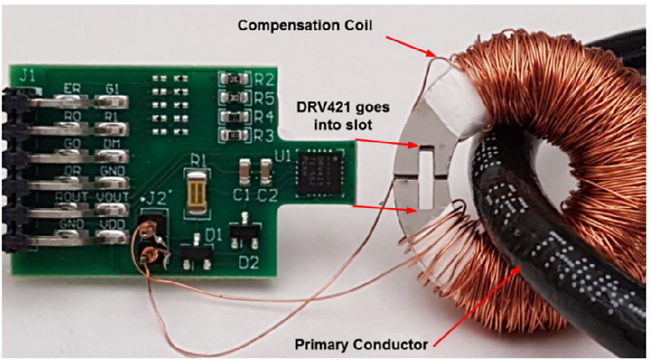
I can't figure how the B-field is like. Do you think that FEMM is enough to understand the behaviour of the B-field, even if it is a 2d magnetic solver, or is it necessary to use a 3d solver like Elmer for example?

Is the core material important, in the sense that influence the performance? A ferromagnetic core like iron is enough? Or more esotic material like nanocrystals are needed?

Also, I see you mentioned a shield to avoid the Earth magnetic field influence the measurement for residual current. How should I put such a shield?

Thank you for your support!

Mattia

  • Hello Mattia,

    Development with the DRV421 will be very challenging.  Not impossible but with so much risk and errors that I would not attempt it.  Below is everything to get you started.

    First see this post.  This will cover the FEMM simulations so you can view the core and the fields being measured.  You can get more real numbers with 3D solvers but for these symmetric simulations I have found that FEMM is good enough.  The field is measured by the DRV421 is shown in the datasheet in figure 52.  The field is not into the package but along side it.  The images in the post should help visualize.

    I cover some of the design Challenges here.  Automatically assuming 500µT/A from your magnetic gain you can expect at 8µT offset error from the DRV421 causing an offset error of 16mA for your current measurement.

    The core material are important for a few reasons.  The higher the permeability the better magnetic coupling, the better external field rejection, the magnetic gain does not impact as much but you can alter the simulation from the link above to see the changes from that.  The air gap matters more for the gain but you can also see this in simulations.

    Let me know if you have further questions after going through some of the links.

  • Hello Javier,

    thank you for your prompt answer. I will check all of your answer in detail. 

    You say that it is very risky: why? I know the project is not easy at all, but the chip should be able to obtain the desired results.

    Also, the biggest thing to understand from my point of view is the core slot where to insert the chip into. I can't understand how can to achieve linearity since the B inside the core slot doesn't seem to be linear.

    I tried to simulate the B inside the core slot, and here are the results:

    The core is taken from the simulation here: 

    How can I achieve a good linearity (and then accuracy) if the B field inside the core slot is not linear? I think I must be missing something...

    Thank you,

    Mattia

  • Hello Mattia,

    So the way this functions is that the DRV421 is creating a feedback loop that drives the field it sees to Zero.  Ideally the ICOMP and the Primary current will couple identical to the magnetic core.  They are not as you will have lower core permeability.  The magnetic core will concentrate the field generated by the signals you are attempting to measure then the DRV421 will drive the current on the ICOMP pins to return it to zero.  So this will close the loop.  The gain from the magnetic core should be equal for the current of your signal and the ICOMP pins.  So the linearity does not need to be there as we only care about the sensors location in the DRV421 and that both signal Icomp and Primary couple in the same way to the magnetic core.