This thread has been locked.

If you have a related question, please click the "Ask a related question" button in the top right corner. The newly created question will be automatically linked to this question.

DRV421: Question about use case condition

Guru 19485 points
Part Number: DRV421

Customer is interested in DRV421 and confirming document.

Please let me know about three points below for use condition.

①About sloa224, summary is described about very careful design.

 Which is this mean "specially of Fluxgate" or "popular of precision analog circuit"?

②About sloa223; 2.1.7 Neighboring Current Rejection Ratio

. This page is described about any effect for external magnetic field.

 If there the case of application problem for external magnetic field, please let me know about reference document and amount of effect and test data, etc. 

③I think that recommended magnetic core module is SC2912(Sumida), is there the other recommended magnetic core module? 

 (I didn't find the information of SC2912 on web)

Best regards,

Satoshi

  • Hello Satoshi,

    Thanks for reaching out.

    1) I would not say the fluxgate or analog circuitry is completely separable in this case. The DRV421 fluxgate senses a magnetic field emanating from a primary current passing through the system’s toroidal-like core. Thereupon some conditioning is done to this sensed field signal, to produce a secondary current in another wire wrapped around the core (compensation coil). If the magnetic core gain, coil windings, and compensation coil inductance (magnetic field conditioning-fluxgate related properties) are properly designed for along with proper device gain setting (precision analog property), the secondary current will have a linear response to the primary current. However, the linearity of the DRV421 output still also relies on analog circuitry that amplifies a differential voltage produced across the sense resistor that is place on the compensation coil line between pins ICOMP1 and ICOMP2.

    2)We do have some application notes regarding the DRV421 device here: www.ti.com/.../technicaldocuments. However, I would recommend using a simulation tool to help with your design as there are several competing design parameters that will affect the measurement performance. One free software package is FEMM. This software is great for illustrating the effects the magnetic core has on the primary as well as nearby stray fields. If you provide us with the primary current range you are intending to measure along with the stray field sources and expected proximity, we can put together a simulation to help you with your design and illustrate the behavior mentioned in that paragraph you posted.

    3) Sumida has halted production on the SC2912 now and for the foreseeable future. We are currently working with some core vendors for a solution to complement our device, but these are still in development. Yet, if you do give us your system conditions, through simulation we can help guide you toward cores that may be available from various vendors. Although, you may need to modify the air gap and compensation coil windings.

  • Hello Satoshi,

    I have not heard back from you. Does your customer need anymore support with the DRV421?
  • Patrick-san

    Thank you for reply,
    I confirmed customer and feedback to you, please see below.

    -----------------------------
    【Customer request spec】
    ・Max Current: 5Arms or 1Arms (±7.07A or ±1.41A)
    ・Fuss scale: Max current ×65.536 (327.68Arms or 65.536Arms)
    ・Min detection current: Max current ×0.05
    ・Accuracy: 1% 
    ・Frequency: 0.1kHz~3kHz
    ・Accuracy classification: Class 0.05_max
    ・EMC test: IEC60255-26 
    ・External magnetic field: 300A/m or 1000A/m
    ・Overcurrent: Max rating ×100 @1sec
    ・Sensor(Core) size: Less than 5cm×5cm×5cm is best, 7cm×7cm×7cm is OK

    【I Answer your question and my additional question】
    ②About FEMM, is below link correct?
    www.femm.info/.../HomePage
    This question mean that customer will use plural DRV421 and coil on one board.
    They worring about mutual external magnetic field.
    (Detailed socket and distance is not fixed)
    ③I contacted to Sumida, SC2912 was already end of design.
    Please let me know about recommended core vendor for matched customer request spec.
    (If not matched request spec, I will confirm possibility of mitigate request spec)
    ④Additional question for datasheet page-30: Figure 67
     ・Which condition is this test data DC or AC?
      If AC, what is frequency condition?
      If DC, is there test data for AC condition? (Customer will use 0.1kHz~3kHz AC)
     ・Is current error mean Full-scale error, correct?
      Or, is ratio error correct?
    -----------------------------

    Best regards,
    Satoshi
  • Hello Satoshi-san,

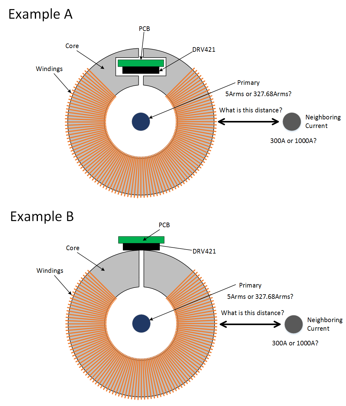
    Before we can proceed with helping on the design, I need to clarify a few things. I have figures below that illustrate the core parameters as I understand them.  With the figures I also have few questions over requirements that did not make sense.  Also, there are two different core examples below.  Please let me know if your customer plans to use one of these or a different shape.

    2)  Yes, you have the correct link.  How close will your customer place their cores next to each other?  Or if they are only using one core, one DRV421 will have to be switched off while the other is operating.

    3) We are working with vendors right now.  Yet those cores are still in the development phase.  However, development should finish soon.  Once they release their part, we will provide their name.

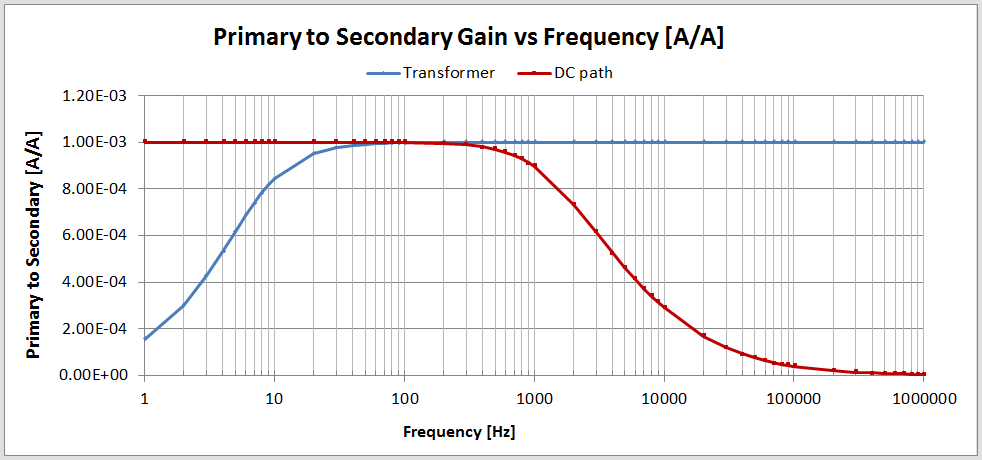
    4) The test condition is DC current with the full-scale error plotted.  For frequencies above 1KHz the core and transformer will determine the primary to secondary gain.  This can be observed in the DRV421 System Parameter calculator listed on this page: http://www.ti.com/product/DRV421/toolssoftware.

    Based on user inputs, this calculator can generate the transfer function curve, such as in the figure below.

  • Patrick-san

    Thank you for kind answer,

    About① and ②, I confirm to customer and probably customer answer is next week.(Because this week is holiday in Japan)
    About ③, I looking forward any update.

    Best regards,
    Satoshi
  • Patrick-san

    Sorry for my reply delay,

    I summarized customer information below.

    ・About core examples, customer is not fixed and no strong request.

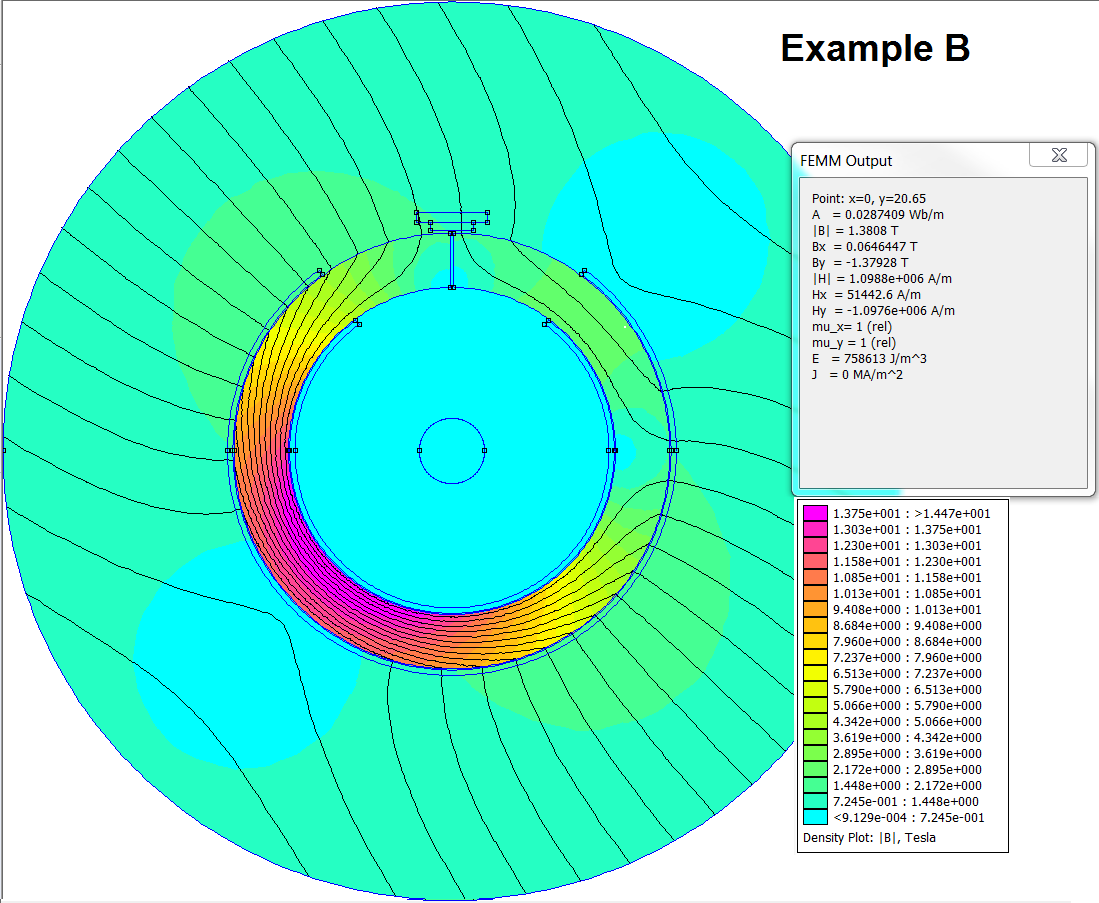
     If Example B is affect by external magnetic field, customer request is Example A.

    ・Current by primary is 0~327.68A. (Over 20A is very short time)

    ・Distance for neighboring current is 2~3cm.

    ・About 300A/m and 1000A/m, customer need both condition. (It is depend on End environment)

    Additional question about ④, is there test data for ratio error?

    Customer is expected for good ratio error spec by DRV4xx series, because AC input is important spec for ratio error.

    Best regards,

    Satoshi

  • Any update on this?
    If you need additional information, please let me know.
    I will confirm to customer soon.

    Best regards,
    Satoshi
  • Hello Satoshi-san,

    I put together a design according to the specifications you gave me. Below, I will go through the process I used. However, I would like to note that your customer may still need to make some modifications to optimize it for their conditions. I would like to note, the core will most likely need to be a custom build. As such, Case B will likely be more expensive to manufacture. Below I will show the contrast in performance between the two configurations.


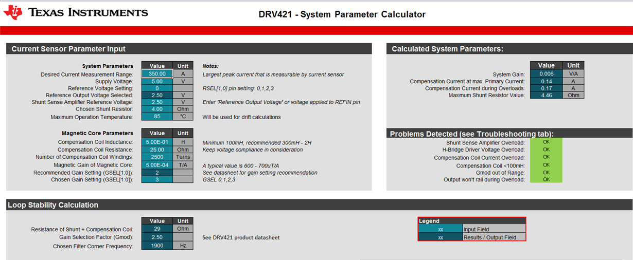
    Step 1: Download the “DRV421 – System Parameter Calculator” (http://www.ti.com/product/DRV421/toolssoftware)

    Step 2: Enter your operating conditions into the calculator tool (see below). For some margin we designed to 350A with a supply of 5 Volts. We put the reference voltage to mid-supply (2.5V).

    Step 3: Choose coil specifications. We chose 500uT/A for the magnetic core gain as this is reasonably close to a value you may find for cores available in the market. As for the turns, at least a thousand turns is recommended. The precise number is determined empirically along with the shunt resistance. We decided on 25Ω and 2500 turns. Your customer may find a better combination. They should not proceed unless there are no problems detected as on the right side of the system parameter calculator window. If lower resistance is desired, thicker wire for the secondary will be required. With that there are a few things to keep in mind. There is finite free space between the primary current wire and the inner surface of the core. Also your secondary winding’s resistance can vary significantly with temperature. At room temperature alone, I estimate you need 20 gauge wire or wire with a larger diameter to fall beneath the 25Ω requirement.

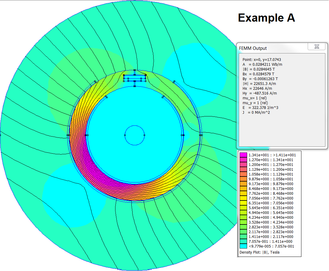
    Step 4: Build a model in FEMM and simulate. I used a script for both examples above. The specifications I used are as follows:

    Core depth (thickness) = 10mm

    Core inner radius = 15mm

    Core outer radius = 20mm

    Air gap = .3mm

    Primary radius=3mm

    Core permeability =14000

    Number of turns = 2500

    Windings angle = 270 degrees

    Pcb height = 0.9mm

    Pcb width = 6.5mm

    Distance from core = 0.25mm

    The scripts I used should be attached below for your convenience. (I also am attaching a powerpoint that will walk you through using the scripts.)  After running the script, I put in your customer’s boundary condition (magnetic field strength H = 1000A/m, B=1.26E-3T). In these figures the Bx term corresponds to magnetic field the DRV421 would sense when no load is running through the primary. This I believe provides a good starting for your customer to work with. I recommend they build their own model with our scripts and then tailor for their desired performance.

    /cfs-file/__key/communityserver-discussions-components-files/1023/8037.Build_5F00_Magnetic_5F00_Core.lua

    /cfs-file/__key/communityserver-discussions-components-files/1023/4118.Build_5F00_Magnetic_5F00_Core_5F00_NoCutout.lua

    /cfs-file/__key/communityserver-discussions-components-files/1023/5224.Magnetic-Cores-No-Cutout-with-FEMM-and-LUA.pptx

    We expect that if your cores are parallel and in line with each other as indicated in your figure above, that the cores will provide a low resistance path for the magnetic field generated in neighboring wires and therefore should have negligible effect on adjacent DRV421 devices.

    As of now we do not have test data for the ratio error.

  • Patrick-san

    Thank you for information,

    Please let me know about simulation results and core module specification below;
    ①About simulation data for example A and B, I think that A is better magnetic, is is correct?
     (I seem that magnetic field is avoid the sensor area)
    ②What is based on the scale of Example A(Pcb height = 0.9mm, Pcb width = 6.5mm)?
     For example, EVM recommended scale, sumida's SC2912 size, etc.
    ③Is core's gap need to count? or, is gap scale have large magnetic effect?
    ④If there recommended core module for Example A, please let me know company name and parts number.


    Best regards,
    Satoshi
  • Hello Satoshi-san,

    1) This is correct, with example A we can avoid stray fields better, but the value is only 3x better. Your customer will need to justify whether this is configuration is worth the cost of the core required. So it will depend upon their application and required accuracy.
    2) This is only as an example and is close to standard pcb thickness of 0.78mm. The sumida module board thickness was not an issue as it did not impact the proximity of the DRV421 to the air gap or the inductance of the core by changing the cross section of the air gap. This would be more of an issue or limitation in Example A and not really an issue in Example B.
    3) The smaller the air gap the better the magnetic gain and external noise rejection. But there are diminishing returns after about between 0.1mm to 0.3mm because the sensor inside the DRV421 is 0.4mm inside the package and the sensor cannot get any closer to the air gap.
    4) We are currently working with a vendor that has this core topology. But we would need to work with them or another vendor to get exactly what is needed for your application. I would like to emphasize this will be a custom part that you will most likely need to contract a core manufacturer to make.
  • Patrick-san

    Thank you for advice, and supporting core vendor.

    If there need additional customer spec/application, I will confirm soon.
    And, I get additional customer request spec(transient current), please see below;
    ・When max current is 5Arms ⇒ 1250A @ 10ms
    ・When max current is 1Arms ⇒ 250A @ 10ms

    About datasheet P30 Figure-67;
    Is there real test data version(condition) of AC(~3kHz) and large current range?
    ※Figure 67 is DC and 100A_max.
    And if there detailed scale for current error, it is more great helpful.
    (Customer want to confirm the condition for 0.001% current error.


    Best regards,
    Satoshi
  • Hello Satoshi-san,

    My answers to your questions are below in blue.

    If there need additional customer spec/application, I will confirm soon.
    And, I get additional customer request spec(transient current), please see below; 
    ・When max current is 5Arms ⇒ 1250A @ 10ms
    ・When max current is 1Arms ⇒ 250A @ 10ms

    These high currents will saturate your core and create an offset which will need to be adjusted for.

    About datasheet P30 Figure-67;
    Is there real test data version(condition) of AC(~3kHz) and large current range? You mean test data for conditions like those posted above? No we do not have.
    ※Figure 67 is DC and 100A_max. Yes, Figure 67 shows DC measurements with 100A being the max primary current.
    And if there detailed scale for current error, it is more great helpful.
    (Customer want to confirm the condition for 0.001% current error. 

    The total current error depends on internal device sources of error as well as the design of the core and the layout of the device. If you look at Figure 69 of the datasheet, the error is significantly higher than 0.001%. The linearity of your core can potentially have a very strong influence on the total error. A core linearity error of 0.1% would be normal. For more information on the errors you may encounter as well as tips on how to design with the DRV421, I would recommend looking at: www.ti.com/.../sloa223.pdf

  • Patrick-san

    Sorry for reply delay,
    Is there any update for recommended core module?

    Best regards,
    Satoshi
  • Any update on core module?

    Customer want to judge OK or NG for use DRV421 solution, these key point is whether recommended core module have or not.

    Best regards,
    Satoshi
  • Satoshi,

    We currently do not have core module to recommended at this time.