This thread has been locked.

If you have a related question, please click the "Ask a related question" button in the top right corner. The newly created question will be automatically linked to this question.

PGA460PSM-EVM: Interfacing PGA460PSM-EVM with Arduino Mega

Part Number: PGA460PSM-EVM
Other Parts Discussed in Thread: PGA460, , ENERGIA

Hi ,

We have been trying to interface PGA460PSM-EVM with Arduino MEGA . We are planning to use 6 PGA460s and recieved all 6 of them.  We tried the following procedures but not able to communicate with the pga460 module.

Our connections as follows 

Arduino MEGA <===> PGA460PSM-EVM

TX1<===> RX ( A voltage divider which converts 5V logic to 3.3V logic 

RX1 <===> TX (direct connection)

PWR <===>12V 1A supply

GND PGA460 <===>GND MEGA <===> POWER GND (common ground for all)

SCK pin is grounded with 10k resistor

The TEST pin is floating assuming the PGA460 works in 3.3V logic state . 

At first 

1. we tried using the ported energia libraries for arduino mega provided by Mr  in this link  unfortunately we got 

ERROR - did not recieve measurement results... 

2. We then tried out this following code 

//note: minimum requirement example used to send a burst/listen command to PGA460


//cmd 0 - p1 burst listen
byte buf0[4] = {0x55, 0x00, 0x01, 0xFE};
//cmd 1 - p2 burst listen
byte buf1[4] = {0x55, 0x01, 0x01, 0xFD};
//cmd 5 - ultrasonic measurement (assume UART_ADDR=0)
byte buf5[4] = {0x55, 0x05, 0xFA}; //change
//cmd 10 - register write decple to time of 4.096ms
byte buf10[5] = {0x55, 0x0A, 0x26, 0x00, 0xCF};
//cmd 17 - broadcast p1 burst listen
byte buf17[4] = {0x55, 0x11, 0x01, 0xED};
//cmd 19 - broadcast p1 listen only
byte buf19[4] = {0x55, 0x13, 0x01, 0xEB};
//cmd 25 - broadcast bulk threshold write
byte buf25[35] =  {0x55, 0x19, 0x88, 0x88, 0x88, 0x88, 0x88, 0x88, 0x84, 0x21, 0x08, 0x42, 0x10, 0x80, 0x80, 0x80, 0x80, 0x00, 0x88, 0x88, 0x88, 0x88, 0x88, 0x88, 0x84, 0x21, 0x08, 0x42, 0x10, 0x80, 0x80, 0x80, 0x80, 0x00, 0x7C};


unsigned char data;
const int buttonPin = 2;     // the number of the pushbutton pin
const int ledPin = 13;      // the number of the LED pin
int buttonState = 0;         // variable for reading the pushbutton status

void setup() { 

  pinMode(ledPin, OUTPUT);
  pinMode(buttonPin, INPUT_PULLUP);
  delay(1000);
  
  // put your setup code here, to run once:
  Serial.begin(19200);
  Serial1.begin(19200,SERIAL_8N2);  // initialize PGA460 UART serial channel SERIAL_8N2
  delay(1000);

  //assume UART_ADDR=0
  //bulk threshold write mid-code values to clear THR_CRC_ERR
  Serial1.write(buf25, sizeof(buf25));
  delay(100);
 
  // set UART_ADDR=0's time decouple to 4.096ms
  Serial1.write(buf10, sizeof(buf10));
  delay(100);
}

void loop() {
    // put your main code here, to run repeatedly: 
  
    // check if the pushbutton is pressed.
    while (digitalRead(buttonPin) == LOW){}
    
    // broadcast p1 burst+listen (non-dependent on UART_ADDR)
    Serial1.write(buf17, sizeof(buf17));
    
    // delay by 100ms
    delay(100);

    //[TODO] print ultrasonic measurement results on terminal
    // read back ultrasonic meas results from UART_ADDR=0
    Serial1.write(buf5, sizeof(buf5));//Serial1
    data = Serial1.read();
    Serial.println(data);
    // toggle red LED
    digitalWrite(ledPin, !(digitalRead(ledPin)));   // turn the LED on (HIGH is the voltage level)

    // repeat loop every second
    delay (1000);      
}

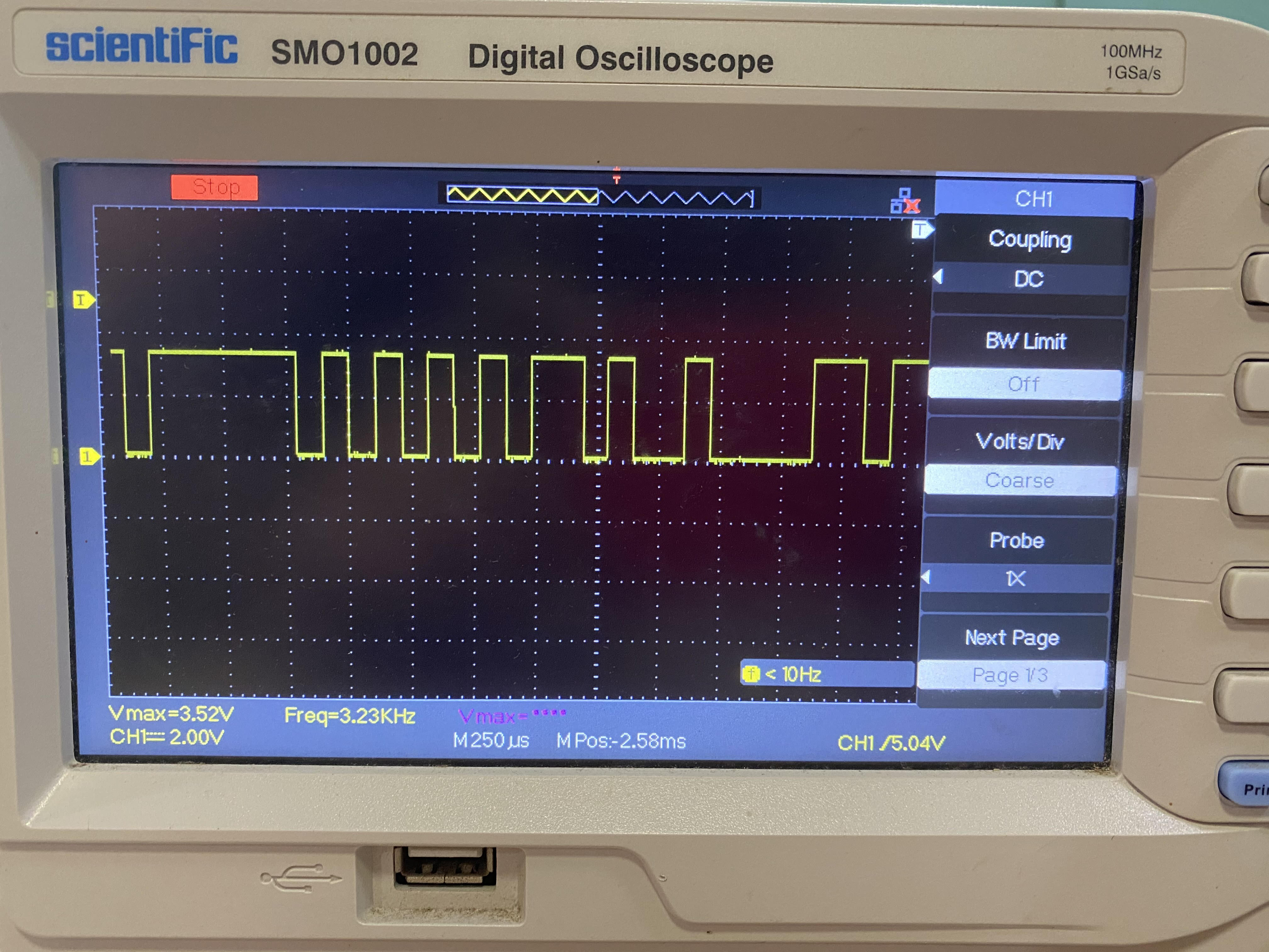
But we had 255 as output in our serial monitor ( even if the wires are removed ) , we think those are garbage values .

3. We just wanted to confirm if there is a communication between PGA460 and Arduino so we used the following example code .

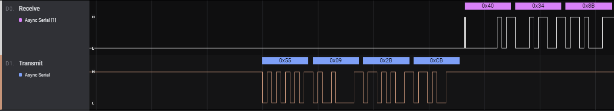
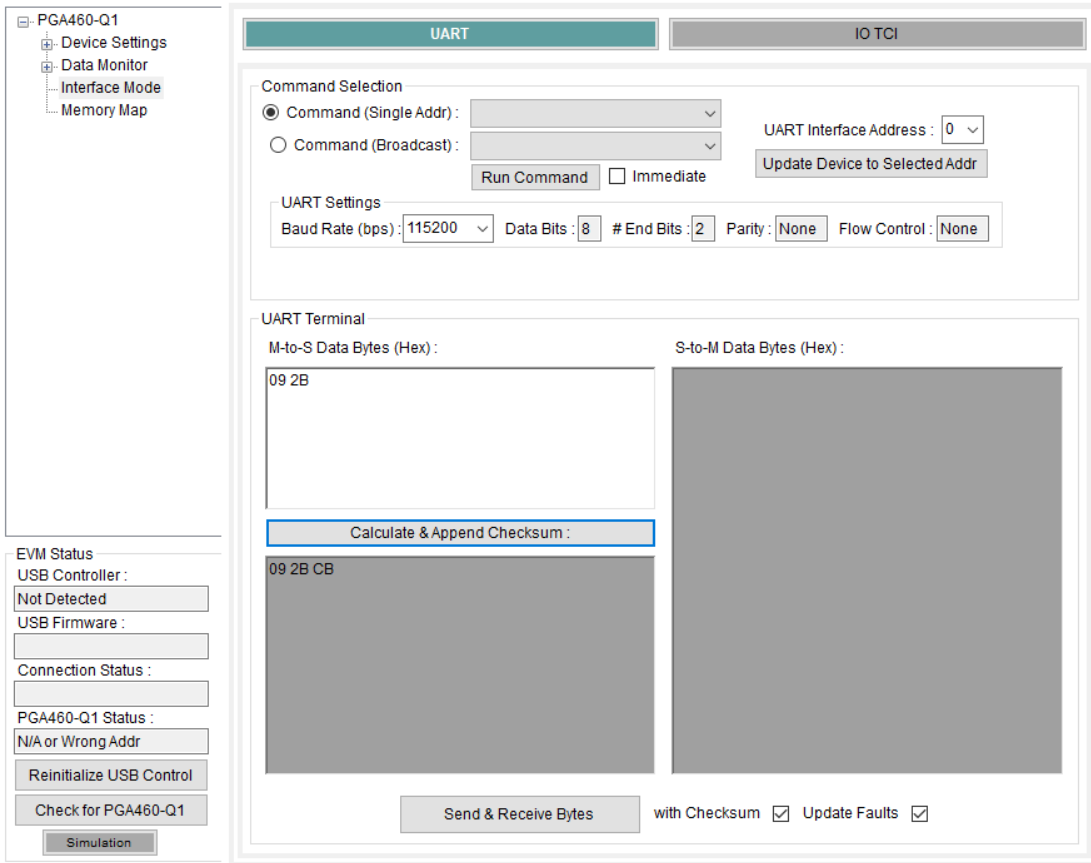
unsigned char WriteByteArray[4] = { 0x55, 0x09, 0x1B, 0xDB };

unsigned char ReadByte1;

unsigned char ReadByte2;

unsigned char ReadByte3;


void setup()

{

Serial.begin(115200);

Serial1.begin(115200, SERIAL_8N2);

}

void loop()

{

Serial1.write(WriteByteArray,sizeof(WriteByteArray));

Serial1.flush();

ReadByte1 = Serial1.read();

ReadByte2 = Serial1.read();

ReadByte3 = Serial1.read();

Serial.println("ReadByte1 = ");

Serial.println(ReadByte1);

Serial.println("ReadByte2 = ");

Serial.println(ReadByte2);

Serial.println("ReadByte3 = ");

Serial.println(ReadByte3);

delay(1000);
}

Again we got 255 in ReadBytes 1 , 2 and 3 . Can you please guide us in establishing a communication?

  • Hello,

    Please see threads 32986133192762, and 3360828

    If you are still having trouble, please provide your test schematic, and any additional details or relevant scope plots. 

    Regards,

    Gabriel

  • Sure will update you.

  • Let me try to be clear now,

    I do not want any confusion with respect to the voltage conversion. So I am using Seeeduino xiao microcontroller  (has 3.3V logic pin UART).

    So my connections are as follows ,

    Sensor pga460<======> Seeeduino xiao uC

    TX<====>RX

    RX<====>TX

    SCLK<===>pulled down 10K common GND

    xiao GND<====> seeeduino GND <====> 12Vdc GND (common GND)

    PWR of pga460<=====> 12Vdc 

    to be noted that The TX pin of pga460 module shows no square waves when probed with CRO

    The RX pin of pga460 recieves the following signal in the picture  

    My TX pin of pga460 is always idle low why?

    (It will also be very helpful if you can tell me the peak response hours of TI)

    Can you please tell me what protocol pga460psm evm works by factory default? 

     The following is my code 

    /*The PGA460 should return three values when using this command:
    •Diagnostic field (0x40) if master transmit was successful
    •Register address value
    •PGA460 generated checksum*/
    
    
    unsigned char WriteByteArray[4] = { 0x55, 0x09, 0x2B, 0xDB };
    
    unsigned char ReadByte1;
    
    unsigned char ReadByte2;
    
    unsigned char ReadByte3;
    
    
    void setup()
    
    {
    
    SerialUSB.begin(9600);
    
    Serial1.begin(9600,SERIAL_8N2);//SERIAL_8N2
    
    }
    
    void loop()
    
    {
    
    Serial1.write(WriteByteArray,sizeof(WriteByteArray));
    
    Serial1.flush();
    
    ReadByte1 = Serial1.read();
    
    ReadByte2 = Serial1.read();
    
    ReadByte3 = Serial1.read();
    
    SerialUSB.println("ReadByte1 = ");
    
    SerialUSB.println(ReadByte1);
    
    SerialUSB.println("ReadByte2 = ");
    
    SerialUSB.println(ReadByte2);
    
    SerialUSB.println("ReadByte3 = ");
    
    SerialUSB.println(ReadByte3);
    
    
    }

  • Hi , any updates? I would also like to know if the SCLK can be pulled down to ground using 10K resistor ? And also I am using 2 stop bit UART since pga460 requires it ! Thanks!
  • Hi,

    SCLK can be pulled down, but it is not necessary. Questions posted in the sensing forum are most likely to reply on week days between 8am and 6pm CST/MST. 

    From thread 3192762 mentioned previously:

    Have you verified that the sync frame is sending properly? If there is an issue with this, the PGA460 will not respond. 

    Regards,

    Gabriel

  • Hi gabriel, The above probe picture I attached consists of TX signal from my master microcontroller. Is that correct ? Is it having the correct sync data? I am sending 0x55 as sync field. And also how can I verify my device is working properly ? Like if the data pins are not damaged ? Also to confirm that the device by default works in asynchronous UART mode?
  • Hi,

    I just connected power supply(12V) and GND to my sensor. I am getting 2.3V in RX pin , but shouldn't I get that voltage in TX pin? is that a problem with the sensor? Note that the pga460 is not connected to any microcontroller, just power supply is given and voltage on RX pin is read! To be added I am not getting any default voltage in TX pin! if that is the case is there any way to reset the pga460 using hardware?

  • Hi ,The Rx pin by default gives 2.3V ! and Tx does not give any idle voltage is this correct?  Please update!

  • Hello,

    I am confering with my colleague, we will  get back to you on this soon.

    Regards,

    Gabriel

  • Sure please update me !
  • Hi,

    I am able to see some data from Serial data read. but , it works only for command register 0 to 8 , when I go for register read I am not sure how to calculate checksum. 

    We sent values

    0x55 ==> sync filed

    0x08 ==> command field (diagnostic command)

    then we recieved 

    0x40 ==> diagnostic field

    0x02 ==> data field (transducer frequency I suppose)

    0x73 ==> data field (decay period time I suppose)

    0xAE==>checksum

    But we are not sure how this data is interpreted. Also we tried recalculating checksum it did not match , please help! Can you also please state how to calulate checksum?

  • That is correct. The 2.3V seen on the RX pin is normal when disconnected. It should be near IOREG when driven. 

    Here is an example working UART communication with the data you are sending:

    In the PGA460EVM GUI 09 2B CB was manually sent, preceded by the 0x55 sync field. Have you tried 1 stop and 2 stop bits?

    Are you able to run the example found in thread https://e2e.ti.com/support/sensors/f/1023/p/840688/3192762?

    Regards,

    Gabriel

  • See pages 32 and 33 of the PGA460 datasheet for details on calculating the checksum. The sync field is not included in the TX checksum, and the diagnostic field is included in the RX checksum. 

    You can check the calculation using the PGA460-Q1EVM GUI. Navigate to the 'Interface Mode' page and check the UART settings, then you can type in the address and  data and it will calculate the checksum. The EVM itself does not need to be connected for this. 

    Example: 

    Regards,

    Gabriel

  • Furthermore, the Energia code where the checksum is computed can be found around line 2200 of PGA460_USSC.cpp. see red below:

    uint16_t carry = 0;


                   for (int i = 0; i < checksumLoops; i++)

                   {

                                  if ((ChecksumInput[i] + carry) < carry)

                                  {

                                                 carry = carry + ChecksumInput[i] + 1;

                                  }

                                  else

                                  {

                                                 carry = carry + ChecksumInput[i];

                                  }


                                  if (carry > 0xFF)

                                  {

                                    carry = carry - 255;

                                  }

                   }


                   carry = (~carry & 0x00FF);

                   return carry;


    carry is the calculated checksum. 

    ChecksumInput is the array of data used in the calculation. 

    ChecksumLoops is the number of bytes the checksum is calculated for. 


    -Gabriel


  • Thank you so much , checksum was the problem. We calculated using the GUI . We need to know how to calibrate the PGA460 for UTR-1440K-TT-R (default transducer) . I tried to use the following thresholds, (Taken from  )

    Can I have any link briefly explaning about all parameters used here! (pga460q1 datasheet doesnot state any parameters in brief)

    /* UTR-1440K-TT-R transducer example register configuration
    byte USER_DATA1 = 0x00
    byte USER_DATA2 = 0x00
    byte USER_DATA3=0x00
    byte USER_DATA4=0x00
    byte USER_DATA5=0x00
    byte USER_DATA6=0x00
    byte USER_DATA7=0x00
    byte USER_DATA8=0x00
    byte USER_DATA9=0x00
    byte USER_DATA10=0x00
    byte USER_DATA11=0x00
    byte USER_DATA12=0x00
    byte USER_DATA13=0x00
    byte USER_DATA14=0x00
    byte USER_DATA15=0x00
    byte USER_DATA16=0x00
    byte USER_DATA17=0x00
    byte USER_DATA18=0x00
    byte USER_DATA19=0x00
    byte USER_DATA20=0x00
    byte TVGAIN0=0x9D
    byte TVGAIN1=0xEE
    byte TVGAIN2=0xEF
    byte TVGAIN3=0x2D
    byte TVGAIN4=0xB9
    byte TVGAIN5=0xEF
    byte TVGAIN6=0xDC
    byte INIT_GAIN=0x03
    byte FREQUENCY=0x32
    byte DEADTIME=0x80
    byte PULSE_P1=0x12
    byte PULSE_P2=0x12
    byte CURR_LIM_P1=0x72
    byte CURR_LIM_P2=0x32
    byte REC_LENGTH=0x09
    byte FREQ_DIAG=0x00
    byte SAT_FDIAG_TH=0xEE
    byte FVOLT_DEC=0x7C
    byte DECPL_TEMP=0x8F
    byte DSP_SCALE=0x00
    byte TEMP_TRIM=0x00
    byte P1_GAIN_CTRL=0x29
    byte P2_GAIN_CTRL=0x29
    byte EE_CRC=0x76
    byte EE_CNTRL=0x04
    byte P1_THR_0=0x41
    byte P1_THR_1=0x11
    byte P1_THR_2=0x11
    byte P1_THR_3=0x10
    byte P1_THR_4=0xFF
    byte P1_THR_5=0xFF
    byte P1_THR_6=0x00
    byte P1_THR_7=0x01
    byte P1_THR_8=0xF8
    byte P1_THR_9=0x20
    byte P1_THR_10=0xC6
    byte P1_THR_11=0x30
    byte P1_THR_12=0x38
    byte P1_THR_13=0x50
    byte P1_THR_14=0x80
    byte P1_THR_15=0x00
    byte P2_THR_0=0x41
    byte P2_THR_1=0x11
    byte P2_THR_2=0x11
    byte P2_THR_3=0x10
    byte P2_THR_4=0xFF
    byte P2_THR_5=0xFF
    byte P2_THR_6=0x00
    byte P2_THR_7=0x01
    byte P2_THR_8=0xF8
    byte P2_THR_9=0x20
    byte P2_THR_10=0xC6
    byte P2_THR_11=0x30
    byte P2_THR_12=0x38
    byte P2_THR_13=0x50
    byte P2_THR_14=0x80
    byte P2_THR_15=0x00
    */
    
    The following were not configured 
    //byte BPF_A2_MSB=0x89
    //byte BPF_A2_LSB=0x52
    //byte BPF_A3_MSB=0xFC
    //byte BPF_A3_LSB=0xCE
    //byte BPF_B1_MSB=0x01
    //byte BPF_B1_LSB=0x99
    //byte LPF_A2_MSB=0x7F
    //byte LPF_A2_LSB=0x33
    //byte LPF_B1_MSB=0x00
    //byte LPF_B1_LSB=0x67
    //byte TEST_MUX=0x00
    //byte DEV_STAT0=0x80
    //byte DEV_STAT1=0x00
    //byte THR_CRC=0xF9

    Can you please let us know why the sensor is returning distance values even if no objects are present?

    Does the user data register have something to do with transducer configuration?

    BPF , LPF and other registers were not configured are they essential?

    Thank you

  • Hello Deepak,

    Thanks for your interest in our products. In regards to your question about clarification about the register settings this should be posted as a new question. This helps our community with similar problems that can be easily searchable. 

    We look forward to your post.

    Thanks,

    Arjun 

    Applications Manager.