⇐ Back to Main FAQ Thread : [FAQ] PLEASE READ : mmWave Forum Guidelines and FAQ Thread
Q1. How to create a new mmwave sensor project from scratch [Project0]?
Answer: Please refer this thread- https://e2e.ti.com/support/tools/ccs/f/81/t/836333
Q2. How to find root-cause if a device goes into fault at DSS/BSS end OR how to find if a device is in fault/bad state?
How to decode the error value mmWave library throws at the application level?
Answer: mmw demo from mmWave SDK checks application status or return values of a function to find out device health and goes into ASSERT if something wrong. Error at DSS is communicated to MSS which says the source code line no. for user to find out root cause.
If BSS goes into some error state or fault then it sends CPU/ESM/Analog Fault asynchronous event [RL_RF_AE_CPUFAULT_SB, RL_RF_AE_ESMFAULT_SB, RL_RF_AE_ANALOG_FAULT_SB] to MSS, MSS application needs to handle these fault. Most of the time recovery from these faults is to reset the device. It can be done by an external processor (notify over nError-out), internal Watchdog, External Watchdog.
At most of the error points, mmw demo sets errCode from the function (like mmwave library) which contains the cause of error.
[bit 31:16] - mmWave Error : MMWAVE_EINVAL to MMWAVE_EINVALIDCALMONUNIT (mmwave.h)
[bit 15:2] - sub system Error : It can be from DSS or BSS, For BSS error codes are defined in mmwavelink.h 'RL_RET_CODE_***'
[bit 1:0] - error level : MMWave_ErrorLevel
One example based on other E2E post (https://e2e.ti.com/support/sensors-group/sensors/f/sensors-forum/708059/iwr1642boost-mmwave-open-configuration-failed-error-code--203554190)

.
Q3. How to send custom user data or intermediate FFT processing data over LVDS?
Answer: Refer related threads-
https://e2e.ti.com/support/sensors/f/1023/p/758435/2803488
https://e2e.ti.com/support/sensors/f/1023/t/759979
Q4. How much time does SBL take to boot up and time to switch to the application?
Answer: Boot up time of SBL depends on the size of SBL image which PBL (primary bootloader) takes to copy content from sFlash to RAM. Default SBL in the SDK takes around 35msec to bootup (measured from nRST: device reset) and SBL to application (mmw demo from SDK 2.1) boot takes around 65mSec. Again these two times vary based on image size.
Here is similar e2e thread https://e2e.ti.com/support/sensors/f/1023/p/767876/2838860#2838860
Q5. What is the format of the data mmw demo sends out over UART?
Format of object data out from application may differ based on SDK version and for different application. These links will explain the basic format of that, most of TI-Rex application provides output data format in their user/developer user guide document.
https://e2e.ti.com/support/sensors/f/1023/t/753460
Even after this you don't find exact output format of any of mmwave sensor application, then you need to dive into source code. DSS generates the object data packet, copies to HSRAM and sends to MSS which further sends it over UART/CAN interface. Look for function having string 'sendProcessOutputToMSS' or 'sendResult' in dss_main.c (most of the application uses similar function name), now you can backtrace to find the packet format.
Q6. Implement the watchdog feature with mmw demo application
Answer: At this thread, code snippet is provided to implement the watchdog feature to mmw demo-
https://e2e.ti.com/support/tools/ccs/f/81/p/835932/3091964#3091964
Q7. How to get input from CCS console?
Answer: Many of times while application development, we need to take input from CCS GUI only. Refer these threads to do that:
https://e2e.ti.com/support/sensors/f/1023/p/838177/3099822#3099822
https://e2e.ti.com/support/microcontrollers/msp430/f/166/t/439318?Scanf-in-CCS-for-MSP430
Q8. How to add sFlash feature in the mmw demo or any other mmwave application?
Please refer this application note- http://www.ti.com/lit/an/swra583/swra583.pdf
Q9. How do I reset the device from the application itself?
You can use the internal watchdog feature to reset the device, refer this thread to implement the watchdog in the application.
Other option by directly writing a register to force a Warm Reset to the device.
|
|
|---|
⇐ Back to Main FAQ Thread : [FAQ] PLEASE READ : mmWave Forum Guidelines and FAQ Thread
Part Number: AWR1843
mmwavelib is composed of a set of radar signal processing functions used in the mmWave SDK demo.
The mmwavelib is provided as part of the mmWave SDK in "C:\ti\mmwave_sdk_03_##_##_##\packages\ti\alg\mmwavelib"
The mmwavelib is provided as source C code and make files are provided to build the src code in a C67x library.
C674x DSP
So, the answer to the question "Can the mmwavelib functions run on the C674x DSP included in the family of xWR1xxx and xWR6xxx sensors?" is Yes.
ARM R4F
What about running the mmwavelib on ARM R4F? Can the mmwavelib functions run on the R4F ARM included in the family of xWR1xxx and xWR6xxx sensors?
In order to answer this question one need to understand the C code used to implement the mmwavelib functions.
Most mmwavelib functions have been implemented with C674x compiler intrinsics in order to optimize the execution speed. This means that it is not possible to build this code with a different compiler.
So, the answer is "No", the mmwavelib functions can't run on the ARM R4F
Hardware Accelerator
Can the mmwavelib functions run on the HWA included in some of the devices of xWR1xxx and xWR6xxx sensor family?
The Hardware Accelerator has a different programming model than standard C code and C674x intrinsics.
So, the answer is "No" the mmwavelib functions can't run on the HWA.
Part Number: AWR1843
Here is a summary of detection for two static objects. There are dependencies on antenna, algorithm, reflectivity of the objects
Depending on an antenna used, the radar data can contain the following information: range, velocity, angle.
If the objects are static, the velocity information does not help to differentiate between objects because both objects have same velocity (they are in the zero doppler bin)
So, if objects are static we are left with range and angle information.
If both objects are at the same range, the range information will not help us differentiate them because it is the same for both objects.
So, we are left with angle information.
Differentiating the objects with the angle information will depend on several factors
1) Antenna Angular Resolution (please see other threads defining this)
If the angle between the two objects is smaller than the antenna angular resolution, then the radar will not be able to detect two objects with traditional fft based processing chain. It may be able possible to detect with higher resolution algorithms such as MUSIC.
If the angle between the two objects is larger than the antenna angular resolution, then we have to consider the following things
2) Does the processing chain support multiple peak detection for the same range bin (same distance)?
Some of the algorithms TI provides detect only one peak (object) for the same range bin. Some other algorithms support multiple peak detection. If the algorithm does not support multiple peak detection it will not be possible to detect the two objects even if the angle between the two objects is larger than the antenna angular resolution.
If the algorithm supports multiple peak detection, then we need to consider the following
3) What are the relative RCS values of the two objects?
The RCS value determines the intensity of the signal reflected by the object. If the two objects we are trying to detect have a very different RCS this means that one of the objects will be much more reflective than the other one. In this case it is possible that in the fft processing the higher RCS side lobes will mask the smaller RCS. In this case it is not possible to detect both objects with this algorithm.
In order to detect two objects with different RCS we many need to use beam forming algorithms.
Thank you
Part Number: IWR6843AOPEVM
Hi TI Sensors Support Team,
I bought and received a IWR6843AOPEVM made by Mistral recently. This board with a on-board heat sink looks different from pictures on TI website. I found it unfits MMWAVEICBOOST and the J2 of IWR6843AOPEVM (a yellow rectangular area in Fig. 1) cannot be dropped in J4 of MMWAVEICBOOST due to the heat sink against J17 on MMWAVEICBOOST (a red circle area in Fig. 1 and a red rectangular area in Fig. 2 ). Per my observation, the displacement of the heat sink results from an uneven PCB edge (a green oval area in Fig 3). Who can I contact to resolve this issue? Thanks
Fig. 1
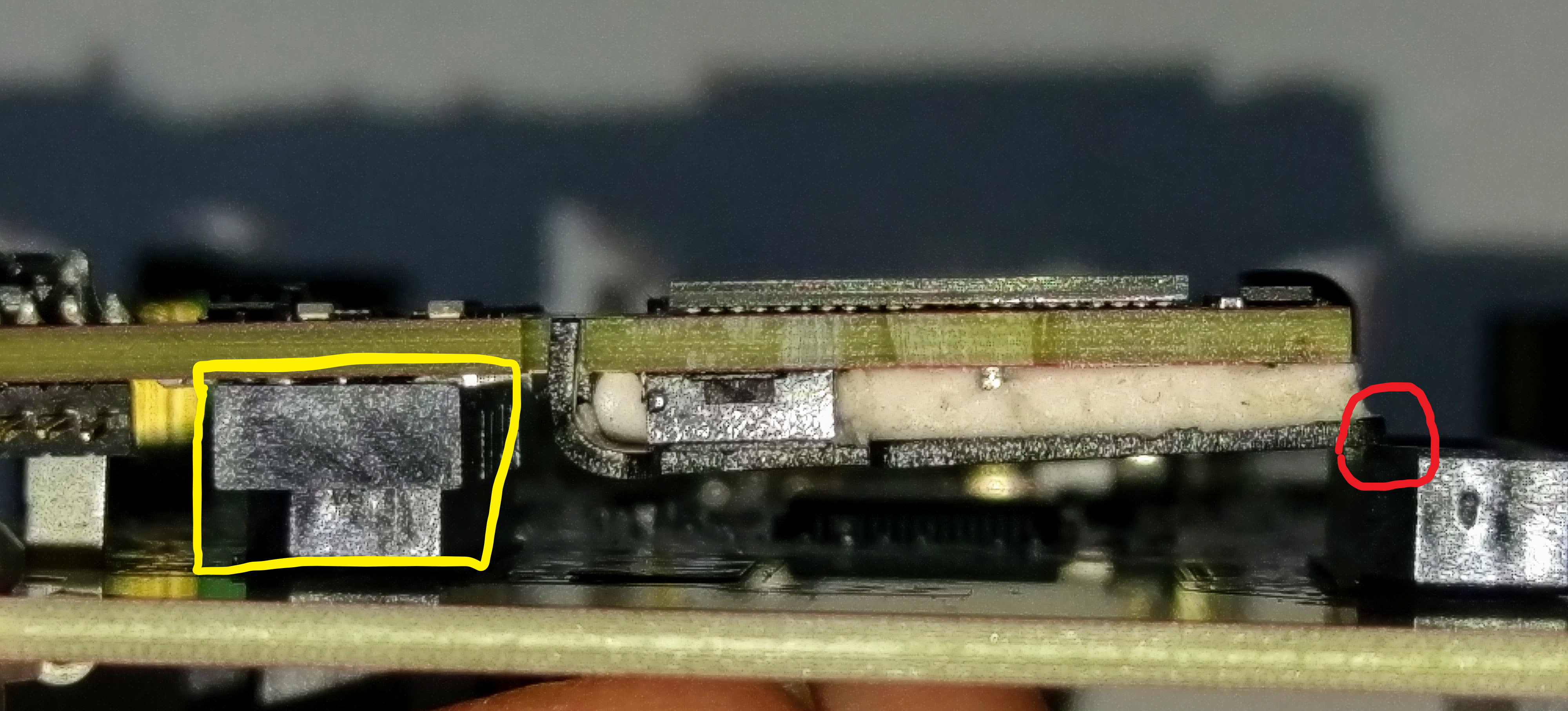
Fig. 2

Fig. 3

CHIEN-CHUNG YU
Part Number: IWR6843AOPEVM
NOTE: The following update will be included in future MMWAVE-SDK releases.
Users can follow the instructions provided below to make the necessary code changes in the SDK themselves
OR
use the pre-updated C file (soc.c) and the updated AOP out of box demo binary: xwr64xxAOP_mmw_demo.bin available in the 68xx AoP - mmWave SDK Demo Lab in mmWave Industrial Toolbox 4.0.1. You will still need follow step-2 given below to re-build the soc lib with source code updates.
Devices affected: IWR6843 ES1.0, IWR6843AOP ES1.0
SW Versions affected: MMWAVE-SDK 3.2.0.4, MMWAVE-SDK 3.2.0.6_AOP
Description: The start-up sequence in the affected MMWAVE-SDK and MMWAVE-SDK AOP releases can fail causing the application to terminate during startup.
The ROM bootloader on IWR6843 ES1.0 devices performs APLL calibration during device boot-up and the status of this calibration is checked by MMWAVE-SDK initialization code. The APLL might not fully settle during ROM bootloader execution causing this SDK check to fail. This does not impact application code since APLL calibration is again performed by the BSS firmware during BSS (aka Radar SS) power-up and SDK checks BSS returned APLL calibration status before starting the application tasks.
In summary, the SDK startup code checks the APLL calibration status twice:
Solution: As mentioned above, the first check is redundant and needs to be removed. Please follow the steps given below to update the code in MMWAVE-SDK 3.2.0.4 (if using IWR6843 ES1.0) and MMWAVE-SDK 3.2.0.6_AOP (if using IWR6843AOP ES1.0). The following updates will be included in future MMWAVE-SDK releases.
Step-1. Make the following modifications in file: C:\ti\mmwave_sdk_03_02_00_xx\packages\ti\drivers\soc\src\soc.c
a) In function SOC_init(), delete/disable the section of code highlighted below (you can put this section inside #if 0 and #endif pre-processor directives to disable it):
if (ptrCfg->clockCfg == SOC_SysClock_INIT)
        {
#if 0
            retVal = SOC_checkBLAPLLCalibration();
            if(retVal < 0)
            {
                /* Error: Expect APLL calibration is done by BL without errors */
                *errCode = SOC_EBLERR;

                /* Free memory and return NULL handle */
                MemoryP_ctrlFree(ptrSOCDriverMCB, sizeof(SOC_DriverMCB));
                ptrSOCDriverMCB = (SOC_DriverMCB *)NULL;
                goto exit;
            }
#endif
b) You will also need to disable the :exit label towards the end of this function to avoid an unused label compiler error.
c) Delete/disable both the function declaration and definition for SOC_checkBLAPLLCalibration() in the same file.
d) Add the new function call SOC_waitAPLLCalibration(…) after SOC_unhaltBCC(…) as highlighted below;
            /* YES: Unhalt the BSS: */
            SOC_unhaltBSS((SOC_Handle)ptrSOCDriverMCB, errCode);

            /* Wait until APLL calibration is done by BSS */
            SOC_waitAPLLCalibration(ptrSOCDriverMCB);
e) Add the following new code (function declaration and body for SOC_waitAPLLCalibration) in the same file, as shown below. This code can be added at the top of this file before other function declarations and definitions.
/* Function declaration */
static void SOC_waitAPLLCalibration(SOC_DriverMCB* ptrSOCDriverMCB);

/* Function definition */
/**
 *  @b Description
 *  @n
 *      This function checks APLL status and wait until APLL clock Calibration
 *      is done from BSS.
 *
 *  @param[in] ptrSOCDriverMCB
 *      Pointer to the SOC Driver
 *
 *  \ingroup SOC_DRIVER_INTERNAL_FUNCTION
 *
 *  @retval
 *      Not Applicable
 */
static void SOC_waitAPLLCalibration(SOC_DriverMCB* ptrSOCDriverMCB)
{
    TOPRCMRegs* ptrTopRCMRegs;

    /* Get the TOP RCM registers: */
    ptrTopRCMRegs = ptrSOCDriverMCB->ptrTopRCMRegs;

    /* Wait until APLL clock calibration is done successfully */
    while (CSL_FEXTR(ptrTopRCMRegs->SPARE0, 17U, 16U) != 0x3);
}
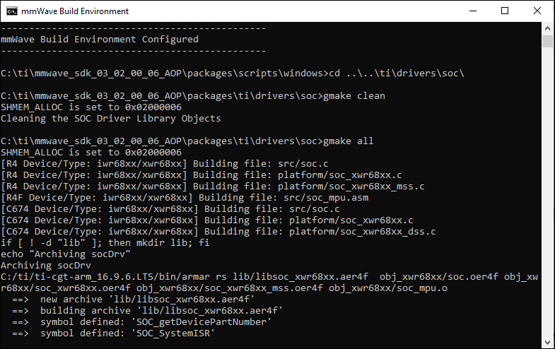
Step-2. Rebuild the soc lib using the steps provided below
a) Open a command window in C:\ti\mmwave_sdk_03_02_00_xx\packages\scripts\windows
b) Execute “setenv.bat”
c) In the same terminal session cd to C:\ti\mmwave_sdk_03_02_00_06_AOP\packages\ti\drivers\soc
d) Execute “gmake clean” followed by “gmake all”.
e) The above steps are also shown in the following snapshots (all from the same command window):

Step-3. Rebuild the mmw demo for the Target device (68xx or 68xx AOP)
a) Either using the build instructions provided in the corresponding SDK user guide, section Building Demo
or
b) Using the mmWave SDK Demo lab for the target device (68xx or 68xx AOP) provided as part of mmWave Industrial Toolbox on TI Resource Explorer
Step-4. Flash the updated mmw demo binary on the target EVM.
Flash and execute the new demo binary on the target EVM as described in the mmWave SDK user’s guide or the mmWave SDK Demo Labs mentioned above.
Hello Everyone,
Please see the below Frequently Asked Questions on the IWR6843 AoP Device and IWR6843AOPEVM.
Cheers,
Akash
Part Number: OPT3001
What is the accuracy of an OPT300x part?
What is the E2E support model for the PGA300, PGA302, PGA305, PGA900, and PGA970?
Part Number: AWR1843
Recently, we have received questions related to detecting static objects at near range (~ 40 cm). This thread will discuss some of the specific details related to this type of detection.
Readers are invited to ask more questions if some of the explanations are not clear.
Let's assume that we are trying to detect static objects such as cones, pipes, 2x4 posts...
Following need to be considered
Antenna, Angular Resolution
Angular Resolution has been discussed in this thread:
https://e2e.ti.com/support/sensors/f/1023/t/681263
It is important to understand that angular resolution is different from angular accuracy. Angular resolution comes into play only when more than one objects have to be detected.
It is also important to notice that angular resolution is a function of the angle and is highest at angle θ = 0.
For example for an antenna that has an array of 4 Rx antennae, the angular resolution at angle θ = 0 would be 2/4 radian, i.e. 28.6 degrees. If MIMO is used with 2 TX, the virtual antennae array can be increased to 8 Rx antennae and the angular resolution at angle θ = 0 would be 2/8 radian, i.e 14.33 degrees.
This would mean that two static objects at same range can only be separated if the angle between the objects is higher than the angular resolution.
Chirp/Profile Configuration
The Chirp/Profile Configuration will define the maximum range and the range resolution
See
https://e2e.ti.com/support/sensors/f/1023/t/633560?
Processing Chain
A Processing Chain will usually process raw data to extract range, velocity, angle information. For static objects there is no velocity information, so all the information contained in the data is part of range and angle domains.
A processing chain may be optimized for static object detection and generate a heatmap only in range/angle domain. This is what the Obstacle Detection Processing Chain described in this TI design implements:
http://www.ti.com/tool/TIDEP-0104
However if velocity detection is also desired, a processing chain similar to the USRR can be used (see in automotive toolbox mmwave_automotive_toolbox\labs\lab0007_medium_range_radar)
Both of the processing chains will detect only onestatic object at a specific range (distance) The reason for this is that both processing chains detect only a single peak in the angular spectrum. In order to detect multiple objects at same distance the angular detection would have to be updated.
Also, we need to keep in mind that the angular resolution will limit the separation of two objects. So, if two static objects are at the same distance at an angle smaller than the angular resolution it will not be able to separate them in detection.
