This thread has been locked.

If you have a related question, please click the "Ask a related question" button in the top right corner. The newly created question will be automatically linked to this question.

UCC24612: About basic operation

Part Number: UCC24612

Tool/software:

Hi team,

I have two questions,

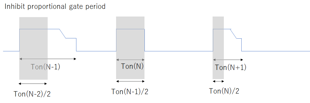
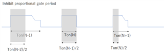
1.I have illustrated the transition of the proportional gate drive inhibition period. Is this understanding correct?

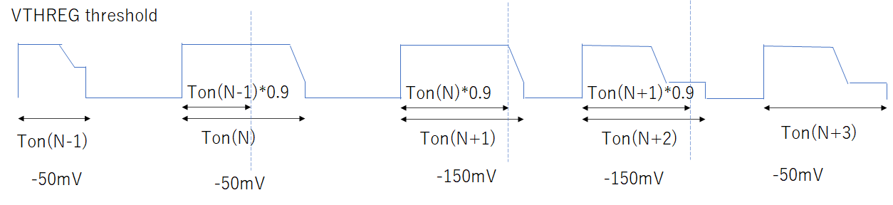
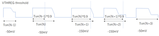
2,I have illustrated the timing of changes in the VTHREG threshold. Is this understanding correct?

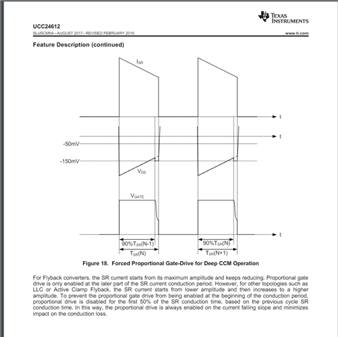
Although the waveforms differ from the actual operating waveforms, I would like to confirm this as IC operation.

  • Hello,

    Your inquiry is under review and I will get back to you shortly.

    Regards,

  • Hello,

    The UCC24612 controls gate drive based on the level of Vds.  Please refer to the figure below.

    1. When VDS voltage goes negative below VTHVGON the FET turns on. VTHVGON = -240 mV typical
    2. The FET gate drive will stay on as long as VDS < VTHVGOff = typical -9 mV
    3. When the FET VDS < VTHREG ( -50 mV) the gate voltage will be at its maximum value ( 8.55 to 10.26 V)
    4. When VDS reaches VTHREG the gate drive will adjust VG to adjust the FET impedance to ensure Ids*Rds = -50 mV
    5. Eventually Ids*Rdson > VTHVGOFF and the gate drive will go low.


    Regards,

  • Hi Mike,

    My question is about the inhibit period transition of proportional gate drive.

    The proportional gate drive starts the second half of the drive pulse determined by the previous pulse width.

    Does the inhibit period transition as shown in the diagram?

    Similarly, does the VTHREG level change as shown in the diagram?

  • Hello,

    Your inquiry is under review and I will get back to you shortly.

    Regards,

  • Hello,

    1.  The middle waveform you have should not occur in a flyback.  Vout/Vin = (Ns/Np)*D/(1-D)

    2.  This feature was added to force progressive FET turnoff for designs where Ids*Rds is always greater than 50 mV in CCM designs. 

    The waveform that you drew below is not correct.

    The following information describes how this feature works.

    Regards,

  • Hi Mike,

    My diagrams differ from the actual operating waveforms.

    Is the inhibition period of proportional gate control always 50% of the previous cycle?
    Does the change in VTHREG level occur when it exceeds 90% of the previous cycle but does not reach -50mV?

  • Hello,

    Your inquiry is under review and I will get back to you shortly.

    Regards,

  • Hello,

    Can you share the waveforms you are seeing?  You will need Vd and Vs across the UCC24612, Vg and VDD of the device.

    Regards,