This thread has been locked.

If you have a related question, please click the "Ask a related question" button in the top right corner. The newly created question will be automatically linked to this question.

TS5V330C: RGB/Composite Switch Guidance

Part Number: TS5V330C

I have read the datasheet for the TS5V330C and I believe it will do what I need it to do.

I want to create a RGB KVM switch to use 1 monitor with 2 1980's era RGB + Sync computers for a group I am a part of and my company want's to be able to offer this solution as it has been asked for.

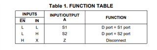
I know this IC supports the video switching for RGB and composite, which is perfect for my needs.

My question is to be able to select the inputs can I just use an arduino to force the pin #1 (IN) HIGH to select the input and bring it LOW to disable that input, and the same to select the input control (pin 15).?

or do I need some type of logic chip to detect a button to do the same as above?  If a logic chip, then which one and are there any references of how to wire it all up?

once I figure this out, i will have to work on finding another IC that will allow me to switch Mouse and Keyboard signals., any direction for this is greatly appreciated as well.

Thank you.

  • Hey Chris,

    You can certainly use an arduino to change the states of the pins. All the IN and EN pins are looking for is a voltages that is either above or below the VIH/VIL thresholds.

    Now with regards to the mouse and keyboards signals, I believe these will just be USB signals. Here's a link to some of protocol-specific USB switches. 
    https://www.ti.com/switches-multiplexers/protocol-specific/products.html#p1389=MHL;USB%202.0;USB%203.0

    In actuality, any switch that has the correct configuration that can support the voltage, frequency and current you're working with should work as well.

    Thanks,
    Rami

  • i should have clarified on the keyboard and mouse.  They are not USB, this will be used for an older computer (really old)..  From the 1980's!

    So it uses a bus mouse (similar to a serial mouse) and a AT/XT keyboard.

    With what you have stated, i would think the TS5V330C would still be able to route the signals as well, even though they are not video.

  • Hey Chris,

    Oh I should have put two and two together there! Sounds like you have a cool project going on. Definitely sounds like the TS5V330C could be used for all your needs. If I'm not mistaken, your at/xt and your bus mouse signals will 5V and very slow (well below 1MHz) so the TS5V330C should work just fine!

    -Rami

  • I have read the datasheet and I see which pins are inputs for each channel and which are outputs.  I have a couple of questions.  Since i want to use a arduino to switch the inputs with code:

    1. Does the EN always go to ground?
    2. Do i only need to force the input switch pin high or low to go to a specific input ?
    3. Do I need like a 1k resistor on the input pin with the arduino to force high and low?
  • Hey Chris,


    Does the EN always go to ground?

    If you don't foresee you needing to switch whether the device is active or not (i.e you always want it active, connected to one of the two channels) then yes, you can certainly just ground the EN pin.

    Do i only need to force the input switch pin high or low to go to a specific input ?

    Yes you'll need to follow the truth table here:

    "H" and "L" are defined as when the voltage on the IN and /EN pins are above and below the VIH/VIL levels listed : 

    Do I need like a 1k resistor on the input pin with the arduino to force high and low?

    As in a pullup or pulldown resistor? I believe this can typically be configured on your arduino. I'm no arduino expert but I have used one in the past. I believe it isn't natively configured so you'll need to configure the pull up first on the GPIO you're using (There's plenty of online code that should be easy to copy + paste the configuration code). Then there shouldn't be a need for an external pullup. 

    Hope this helps and let me know if you have any other questions!

    Thanks,
    Rami

  • I will have a need to be able to disable the IC when selecting to another input other than 1 or 2.  I have a expansion board using the same IC to be able to use a 3 and 4 input for RGB signals, so being able to disable the entire IC with the EN signal is perfect.

  • Perfect! Which means, and I'm sure you've spotted this, but you cannot just ground your EN pin then. You'll need to also drive that signal with one of your GPIOs

  • yes, i am driving both IN and EN with a GPIO pin.  I did notice that all I have to do is bring the EN pin HIGH and it disables the IC completely.  Correct?