This thread has been locked.

If you have a related question, please click the "Ask a related question" button in the top right corner. The newly created question will be automatically linked to this question.

Fail safe design to drive a 24V relay when two mosfets are energised - AND logic

Other Parts Discussed in Thread: CSD17483F4, TINA-TI

Please suggest the mosfet configuration for below requirement -

24V Relay details -

1. Rated voltage (Vdc)- 24V

2. COIL resistance – 350 ohm

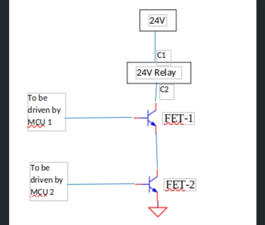
Both the FET's must be independently driven by 2 different MCU's. When both the FET's are switched ON, the 24V relay should be energized.

Please suggest FET's and connection configuration.

When power is cut off both the FET's shall be switched off.

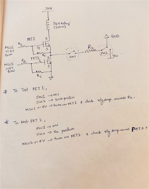
Also provide procedure for self-check test of each FET's

  • Hello tilak kc,

    Thanks for your interest in TI FETs. Based on your requirements, the current thru the 2 FETs in series is only about 70mA (24V/350Ω). How well regulated is the 24V input to the relay? What is the output high voltage level from the MCUs? You will need at least a 30V N-channel FET for this application. If the 24V is not well regulated or there are transients that exceed 30V, then you may need to consider a higher voltage FET. As a starting point, I'd recommend the CSD17483F4, 30V FemtoFET. This is our lowest cost and smallest FET for this application. It requires a minimum gate drive voltage of 1.8V from the MCU. The implementation should be fairly simple with the drain of the top FET connected to the relay coil and its source connected to the drain of the bottom FET. I'd recommend a small value (1-5Ω) series gate resistor for each FET and a larger (10kΩ - 100kΩ) pull down resistor from the gate to source on each FET to make sure they are off if the gate is left floating. I'm not sure how you would perform a self-check of the FETs. Please review and let me know if you have any questions.

    Best Regards,

    John Wallace

    TI FET Applications

  • Hello John Wallace,

    Thankyou for your reply. I will consider the above comments .

    Also,

    Can you look into the document attached for self check for each of the FETs. Request you to update or comment on the attached procedure for self test.

    You can also suggest SW1 and SW2 suitable for below.

  • Hi tilak,

    In order turn on FET1, FET2 must be turned on to pull the source of FET1 to GND. If FET2 is off, then the source of FET1 is floating and there is no way to turn FET1 on. Here's what I suggest:

    • In your diagram eliminate SW2 and connect R6 directly to VCC
    • Test FET1 & FET2 by turning on both FETs (SW2 & SW3 closed) with SW1 open and measure the voltage drop across the relay coil (24V).
    • Test FET2 with SW1 closed, FET1 off  (SW2 open) and FET2 on (SW3 closed), measure current thru R6 (VCC/R6). Measure voltage drop across relay coil (0V). If FET1 is shorted, then the voltage drop across the relay coil will be 24V.

    I created a simple TINA-TI simulation that I have attached that you can try. I simply used switches to control the voltage applied at each gate and I assumed VCC = 1.8V. You can change the state of the switches by clicking on them. I also added SW4 & SW5 to allow you to short one or both of the FETs as this is the most typical failure mode for a power MOSFET. Run a DC analysis to calculate nodal voltages and use the probe to see the voltage at any node in the circuit. The switches are currently configured to have both FETs on.

    You can download and install TINA-TI at the link below:

    https://www.ti.com/tool/TINA-TI?keyMatch=TINA

    Let me know if you have any questions.

    Thanks,

    John

    Relay.TSC

  • Hi tilak,

    Following up to see if your issue has been resolved. Please let me know.

    Thanks,

    John

  • HI tilak,

    Since I have not gotten a response from you, I assume your issue has been resolved and will close this thread.

    Thanks,

    John

  • Hi John Wallace1,

    Sorry for the late reply.
    Thankyou for your relay.TSC design.
    I tested the above circuit in TINA and was testing different failure conditions.

    I wanted to monitor voltage at VM pin in different FET short scenario.
    When the bottom FET is short - VM pin will be at 0V
    when the top FET is short VM pin will be at 24V
    and if no short in both FET's , VM pin will be at 7.2V around.

    The VM pin will be monitored using ADC pin in MCU, Can you suggest a way to limit the voltage of VM pin at MCU pin.
    Either by using voltage divider / zener diode to prevent overvoltage damage at MCU pin.

    Thanks,
    Tilak

  • HI Tilak,

    I think a resistor divider should be adequate to protection the ADC pin on the MCU. Of course, you can also add a zener diode to clamp the voltage.

    Best Regards,

    John

  • Hi Tilak,

    Following up to see if your issue has been resolved. Please let me know.

    Thanks,

    John

  • Hi Tilak,

    Since I have not gotten a response from you, I assume your issue has been resolved and will close this thread.

    Thanks,

    John