This thread has been locked.

If you have a related question, please click the "Ask a related question" button in the top right corner. The newly created question will be automatically linked to this question.

MUX506: Confused by analog multiplexer's leakage-current datasheet specification

Part Number: MUX506

Dear community,

I want to build an analog front-end with a 16 channel multiplexer. On each multiplexer input, there will be a voltage divider made from resistors. On the multiplexer output, there will be an op amp buffer and later on a 12-bit ADC. The signals are low frequency (<100Hz). (The schematic below only serves as a rough illustration. Part numbers, resistor value, the source voltage differ)

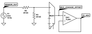
Now what I'm concerned about is the offset introduced by the multiplexer's leakage current. So for selecting the right part, I will need to make some calculations about the worst-case offset. The application is for an industrial product and I need to consider worst-case value from full temperature range. I already have the correct formulas by hand to calculate the offset. However, what confuses me is the specifications in the datasheet (MUX506):

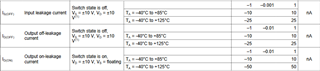
The datasheet specifies three different leakage currents. I am interested in the leakage that occurs for a particular channel during measurement (when the switch is on). So initially, I though that I just have to consider the Output on-leakage ID(On). Then I noticed that the datasheet uses the term "switch".

Since a 16 channel multiplexer contains 16 switches (only one can be active at a time, and all switch outputs are connected) do I also need to consider the Output off-leakage ID(Off) in my calculations? e.g.:
total_leakage_current = ID(On) + 15 * ID(Off)? Or is this somehow already contained in the specifications of ID(On)?

I asked this question previously on electrical engineering stack-exchange (link), where the community suggested that ID(On) + 15 * ID(Off) is the correct leakage value. However, on the Texas Instrument Precision Lab Series about multiplexers (link) at 3:37 the formula for calculating leakage-offset only considers ID(On).

So now I am even more confused. Can anybody tell me which answer is correct (and maybe explain why)?

  • Hi Dominik,

    Thanks for reaching out here! With respect to calculating total leakage to determine measurement offsets, the stack-exchange answer is the way to go in this particular case. When any of the switches are off, whatever leakage current is present will still flow through the load resistance. Since this is a measurement application, you want to account for leakage from both the on channel and the off channels - which is why the stack exchange suggested ID(On) + 15 * ID(Off).

    There's a relevant, lengthy discussion on this topic on an older E2E for a different device, but the concepts are still the same. 

    Let me know if this helps or if anything else is needed here!

    Regards,

    Alex

  • Hi Alex,

    Thank you for the fast response. Ok I will then further on proceed with the suggested leakage current formula ID(On) + 15*ID(Off). But what still bothers me is the fact that every TI article / forum thread  / video that I could find (the one you linked also) calculates measurement offsets due to leakage solely with ID(On). I think this is quite misleading and was a large contributor to my confusion.

    In fact, for many multiplexers, the contribution of (N-1) * ID(Off) will even be larger than ID(On). This can lead to big mistakes, even when calculating with typical values at 25°C.

    Is there an explanation for this?

  • Hi Dominik,

    The TI datasheet outlines each spec for the sake of simplifying analysis and to encompass all applications. There may not always be a need to calculate the combined leakage in this fashion. The datasheet serves as a reference for these types of calculations and it is up to the customer/end user to anticipate what their system requirements are. 

    Hope that helps and good luck on the design!

    Regards,

    Alex