This thread has been locked.

If you have a related question, please click the "Ask a related question" button in the top right corner. The newly created question will be automatically linked to this question.

CD74HC4051-EP: estimating power consumption

Part Number: CD74HC4051-EP

Hi,

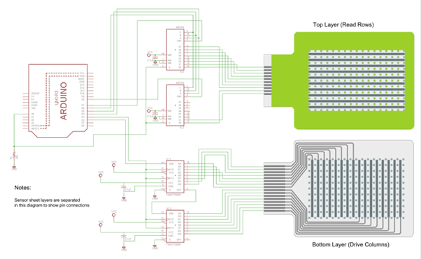
I am trying to estimate the power consumption for this multiplexer, but I am not sure I there is a more suitable method for doing this.

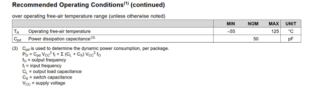
From the data sheet, I require a voltage of 5V to be supplied to the multiplexer, and I approximated the current consumption as 50mA (from the continuous current through VCC or GND) as this was the largest value of curent given.

Using P = I*V, I therefore got a power consumption of 5*50mA = 0.25W.

Is this a reasonable calculation or approximation for this component, or should different values or method be used?

Thank you :)

  • OK makes sense thanks a lot for clarifying this.

    Also, if I had multiple of these multiplexers in a digital circuit connected to a microcontroller, and each multiplexer is enabled sequentially, for the total power consumption in the circuit would I still need to account for both of them at the same time (or just the one that is enabled)?

    Thanks again!

  • The current flows only through an enabled switch.

  • Hi Sama,

    Thanks for reaching out here! 0.25W is pretty close for what you can expect. Here's a good resource for how to solve for CMOS power consumption

    [FAQ] How do I Calculate Power Consumption or Current Consumption for my CMOS Logic Device?

    The capacitance will vary based on whether the switch is in the ON or OFF state. You would take the worst case value here, which would be the Cf + Cio. Max current through the switch is defined as 50mA. And for the latter question, you would just account for power consumption of the enabled switch. 

    Regards,

    Alex

  • Hi,

    Thanks a lot for your reply, this was really helpful!

    I'm still a bit unsure about the dynamic power consumption calculation, as the data sheet doesn't provide information on the input frequency (fin) or output frequency (fout).

    Are these related to fmax (180MHz) given in the data sheet, and if so how? There don't seem to be any other frequency values given which is why I was thinking this one had to somehow be use, but this may be wrong...

    I am also assuming that the fmax given is the maximum sampling frequency of the multiplexer, so then maybe using the Nyquist sampling theorem the input frequency to the multiplexer (fin) would have to be fmax/2?

    Again, I am not sure if this is a valid assumption, or how the input and output frequencies for the multiplexer would be calculated, as all of the other key parameters for the dynamic power consumption are given in the data sheet apart from these.

    For context, the multiplexer is connected to a matrix of force sensitive resistors, although I've read that the sampling frequency of the sensors and the input frequency of the multiplexer are independent so don't think that needs to be used.

    Would be extremely grateful for any help on this, and thank you again!

    Sama

  • Hi Sama,

    Sorry for the confusion here! Let me back track a bit. Your original estimation of current consumption was pretty close. This is looking at the static power consumption which I believe is what you're interested in for your application. We want to look at Icc though, which is spec'd 160uA or 320 uA based on supply conditions. So you're looking at 5*160uA or 5*320uA depending on your application. Of course, this leads to a very small value because the current through the switch generally does not flow through VCC or GND, so it is not really consumed.

    Calculating power dissipation is a different calculation so let me know if that is needed too!

    Regards,

    Alex

  • Hi Alex,

    Many thanks for your reply!

    Ok, so I used the 'continuous current through VCC or GND' of 50mA for the current, but this is different to Icc that you've given above so just wanted to confirm that I should use those lower values for static power consumption?

    I am also struggling with the overall power consumption (i.e. static + dynamic) so need to find the dynamic part.

    The part I am not sure about from the equations in the link you attached showing how to calculate power consumption, is the input and output frequencies (fin and fout).

    So for context, I actually have multiplexers connected to the rows of my sensor matrix, and shift registers connected to each column that sample the data. I was thinking that the input frequency(fin) for both the shift registers and multiplexers would be same as the sampling frequency I decide for my sensor matrix - would this be a valid assumption?

    Also would the output frequency for both these components also be equal to the input frequency (same as sampling frequency of sensors)?

    I was thinking this as the sensors are directly connected to the shift registers and multiplexers the shift register frequency would set the sampling frequency of the sensors and also the multiplexers.

    My circuit would look something similar to this if that helps at all (multiplexers connecting rows, shift registers connecting columns):

    The shift registers I am using are: https://www.ti.com/lit/ds/symlink/sn54hc595-sp.pdf?ts=1703224270900&ref_url=https%253A%252F%252Fwww.google.com%252F

    Thanks again for your help, would be great if you had any advice on this to be able to find the dynamic power consumption!

    Sama

  • Hi Sama,

    Correct that you would use the smaller Icc values. We're interested in supply current in this case. In the previously attached FAQ, you'll see a calculator for obtaining power consumption near the bottom of the page. The sample Icc provided is in the uA range, so this checks out. 

    In fact, the previous FAQ is related to CMOS logic devices. Our switches are passive devices so you won't need to worry about factors like input/output frequencies here. Sorry for the confusion. 

    The power consumption for our switches can actually be found using the following formula as found in this E2E

    which simplified to 

    So, we can use 5V * 160uA + 1 * 50mA^2 * 240 = 0.6758W

    Regards,

    Alex

  • Hi Alex,

    Thanks again for your reply!

    Ah ok, so are the multiplexers and shift registers aren't CMOS components? I was confused by this, as both the multiplexer (https://www.ti.com/lit/ds/symlink/cd74hc4051-ep.pdf?ts=1703216081375) and shift register (https://www.ti.com/lit/ds/symlink/sn54hc595-sp.pdf?ts=1703224270900&ref_url=https%253A%252F%252Fwww.google.com%252F)  data sheets do mention they use CMOS technology, but it also makes sense that they are passive devices...

    So the formula above adds the static power consumption with the losses of the device itself (using resistance of switch), so should N not be the number of channels (8) or is it 1 as only one channel is active at a time?

    I am also not sure how this would be applied for the shift register, as the data sheet does not give an 'Ron' resistance? - would you please be able to help with this component too?

    Thank you again,

    Sama

  • Hi Sama,

    The passive nature of this device allows us to simplify many calculations, such as power consumption. As far as N is concerned in the calculation, we only have one active channel at a time so we just choose 1 for this value. 

    Secondly, are you asking about power consumption for the shift register? If so, I'd need to move this thread to the appropriate group that handles this device. Let me know if I'm understanding correctly and I will do so!

    Regards,

    Alex

  • Hi Alex,

    Many thanks for your reply!

    Ok this makes sense for the multiplexer, is there a reference to where this equation for power consumption (e.g. a paper or website) comes from at all? (no worries if not!)

    Yes please, well I wasn't sure if the same equation could be applied for the shift register due to not having the same parameter values in the data sheet... but essentially yes, I'm also stuck on the power consumption for the shift register!

    Thank you :)

  • Hi Sama,

    This formula was derived by a previous applications engineer from a simplified linear model of the mux (i.e. an RC model). 

    It comes from the idea that the power consumption on the part is a combination of the products of current x voltage at every pin. 

    I'll go ahead and loop in the shift register team now!

    Regards,

    Alex

  • Hi Sama,

    Use the original FAQ to calculate the power consumption for the shift register: https://e2e.ti.com/support/logic-group/logic/f/logic-forum/875721/faq-how-do-i-calculate-power-consumption-or-current-consumption-for-my-cmos-logic-device

    If you have any problems please let me know. It would also be helpful to give me the part number for the shift register.

    Best,

    Malcolm

  • Hi,

    Many thanks for your reply.

    I am using a 74HC595 shift register (https://www.ti.com/lit/ds/symlink/sn54hc595-sp.pdf?ts=1703224270900&ref_url=https%253A%252F%252Fwww.google.com%252F).

    I think this is a CMOS component, but am struggling to work out the dynamic power consumption using the values given in the data sheet.

    It would be great if you could please help with the power consumption calculation - thank you!

  • Hi Alex,

    Sorry to double check this again, but for the multiplexer (https://www.ti.com/lit/ds/symlink/cd74hc4051-ep.pdf?ts=1703216081375), the data sheet shows this equation for the dynamic power calculation:

    Can this then be ignored, i.e. still don't need to find the dynamic power consumption using input and output frequencies (which not sure about) in this way?

    I wanted to ask this again just to be sure, otherwise will use the equation from before with only static power consumption and power consumption of the multiplexer itself while switching.

    Thanks,

    Sama

  • Hi Sama,

    Let n = number of inputs that are switching. You have 2 clocks and 8 data inputs, so let's say that we have 10 total inputs that are switching (n = 10).

    We have Cpd from the datasheet at 400 pf:

    Let's say that VCC = 5V as you mentioned in your original post. Finally, I am not sure what frequency your input signals are switching at, but let's say they are switching at 1MHz. This is not a parameter you find in the datasheet since it's inherent to your system (you control the frequency of the input signals). Thus are dynamic power consumption would be:

    Pd = n x (VCC^2) x Cpd x (Switching frequency of inputs) = 10 x 25 x 400E-12 x 1E6 = 0.1W

    For static power, ICC max = 8uA:

    So Pstatic = 8E-6 x 5 = 40uW. 

    Best,

    Malcolm

  • Hi Malcolm,

    Thanks a lot this is really helpful!

    I had a couple of questions:

    First, for the number of inputs switching is that always the total number instead of say 1 if only one input is changing at a time for the shift register?

    Also, you mention that the input frequency is something that can be set - if the shift register is directly connected to sensors that are sampled, would the lower bound of the input frequency to the shift register be equal to the sampling frequency of the sensors (assuming the input frequency of the sensors can't be lower than how quickly the sensors are sampled)? - wanted to ask if this is a valid assumption to make.

    Thank you :)

  • Hi Sama,

    1. It's how many inputs are changing per unit of time, usually defined as one clock cycle. So how many inputs change per clock cycle fed into the device.
    2. It is hard to see your circuit picture above. But assuming you mean the inputs of the shift register are connected to the outputs of the sensor, then yes, I would use the sampling rate of the sensors here.

    Best,

    Malcolm

  • Hi,

    Many thanks for your reply, this is really helpful.

    I am also confused on the communication/data transfer for the shift register. If the shift register is connected to the microcontroller in this type of setup (see diagram below) what communication protocol is being used?

    I am a bit confused as to how data is transferred to the microcontroller after the shift registers help to read specific sensor elements in the matrix - I have looked into SPI, I2C etc but not sure if any of those apply for the shift register?

    Thank you.

  • Hi Sama,

    I'm a little confused as to what you are asking and I suspect this question goes beyond my area of expertise. SPI is probably the most commonly used protocol to drive these sorts of shift registers but that's up to the person designing the system.

    Best,

    Malcolm