


Tool/software:
Hi TI, This is Steve
I need to control a system which include SBC (single board computer) and battery
1.
The battery have a spst switch, after measurement
This spst, one contact is pull up 4V with 300K ohm and the other one is connect with GND
I think the MCU inside the battery is sensing this pin to trigger the external GPIO interrupt to turn on/off the power (VDB is 4V~5V)
2.
The SBC have the operating system
3.
The SBC power source is from battery, push the battery spst to turn on the power, and push again to turn off the power,
Because of the point 2 said, the OS is include in SBC, so turn off the power directly will make damage for the SBC.
I have a idea, but I'm not sure this is correct or not
The step is shown as below:
a.Separate the SPST to SPDT,turn the circuit as below, (the switch is shared but the route-trip path are different) VDDs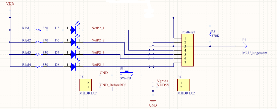
b.Before battery turn on, the circuit path takes the SPDT's NC, so the user push the switch button, the battery will turn on.
circuit path route: Vgpio3->NC1->COM1->SW->COM2->NC2->DGND
c.After battery turn on, the circuit path takes the SPDT's NO, so the user push the switch button, the battery power will not turned off.
circuit path route: Vdd5V->NO1->COM1->SW->COM2->NO2->R75(MCU will sensing if the switch is push or not)->DGND
remark: make sure R75 value is correct or not, the voltage need to bigger than MCU's Vih.
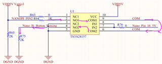
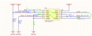
d.According these three point mention above, relay could be used, so I found the IC "TS3A24157"
e. the full design file is shown as below, is there I need to modify?
