A related question is a question created from another question. When the related question is created, it will be automatically linked to the original question.
If you have a related question, please click the "Ask a related question" button in the top right corner. The newly created question will be automatically linked to this question.
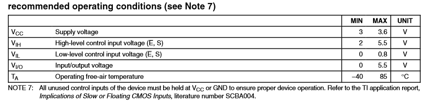
The use case you show above is valid for this TS3L110 signal switch. When you continue with your design make sure that you are following the recommendations in the datasheet.
What is the typical use case for TS3L110? Is it usually used only to switch signals between the PHY and the magnetics?
I am looking to use TS3L500 for an application where I need to either connect to a line, or forward it (shown in the diagram below). I am worried that adding the additional transformers and the switch resistance in the MUX will attenuate the forwarded signal too much, do you know if this is the case?
The typical use case for the TS3L1100 is to route signals from one source to two different places or isolate a bus.
I do not know if the additional transformers and the TS3L500 switch resistance will attenuate the forwarded signals "too much." I do know that max attenuation you could see through the TS3L500 mux is 6 ohms.