This thread has been locked.

If you have a related question, please click the "Ask a related question" button in the top right corner. The newly created question will be automatically linked to this question.

Power supply switching for 28V using N-MOSFET

Other Parts Discussed in Thread: CSD18534KCS

Hello everybody, 

                            I would like to state that I have a circuit as shown below.

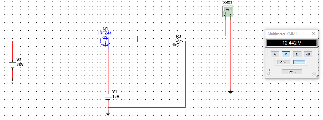
The problem which I am facing is that I cannot find out why the 16V supply is given to the gate of the MOSFET. There is a boost circuit implemented on the gate side. When the circuit is not working then only 16V are coming on the gate. So, that is why I have placed a 16V battery on the gate terminal. When the gate voltages is 16V then the output voltages is 12V, but I cannot find out why is that. In front of this MOSFET is connected a DC-DC converter which has a minimum operating voltage of 18V.

I cannot understand it.

Can anyone please help me?

Regards,

  • Ali,

    Thanks for asking the question.

    First I would like to point out that TI also has 60V MOSFETs, see table here, www.ti.com/.../products.html

    As for your question with regards to the circuit about, the reason you are seeing 12V is because the FET must be operating in the linear region and almost acting like an LDO.
    If the FET was fully on in the saturation region then the FET resistance would be so low compared to the 1kOhm resistor that the voltage on the source of the FET would be almost 28V. An nch FET requires a +ve voltage from gate to source to turn on, in this case the voltage now would be -ve (28V on the source and 16V on the gate) and so the FET would turn off, this can not happen.
    As such your device is operating in the linear region, not fully on or off, acting like a variable resistor, see fig 2 in the CSD18534KCS datasheet, the circuit has obtained an equilibrium current which is why you see 12V .