This thread has been locked.
If you have a related question, please click the "Ask a related question" button in the top right corner. The newly created question will be automatically linked to this question.
Tool/software: Code Composer Studio
Hi,
I was building a custom board with the CC2640R2F chip. I am trying to program the chip via the LAUNCHCL-CC2640R2 board. I use following connectors: GND, 3.3V, RESET, TMS, TCK,TDI and TDO.
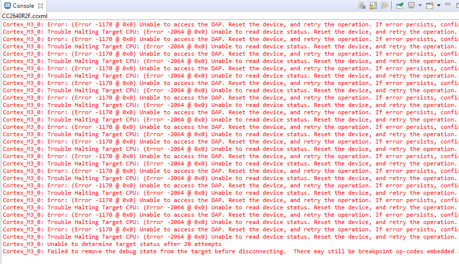
Unfortunately the error "Unable to access the DAP" appears.
When I am testing the communication to the chip via target configuration inside of Code Composer Studio, it shows me no errors.
I am a little bit lost and I hope you can help me.
Thank you
Christian
Those are the correct connections.
To confirm I just setup a CC2650 LaunchPad and made those connections to my CC2640R2 LaunchPad.
I ran the Test Connection tool from inside CCS and that passed.
I then tried the pwmled example from the SDK and that worked fine as well:
Seems like there is a bad or noisy connection.
In CCS if you own the .ccxml file in your project (probably in the targetConfigs folder) you can click on the button there to test the connection and see if it gives you any more info.
Regards,
John
Christian,
I spoke to some people and have a couple things for you to try.
SmartRF
Different JTAG settings
Save the changes and try connecting.
Regards,
John
Hi John,
thank you for your answer. I tried out your suggestions:
I have built two of these custom boards and both have this error.
It looks like that flashing of the chip is working, but then the CPU doesn't start.
Christian
Interesting.
Can you try the following:
Regards,
John
Well that is good. You actually connected to the DAP without an error.
If you go back to the Debug View and select the Cortex M and connect what happens?
If it connects ok could you then try clicking on the load program button and select the .out from your project.
It still fails with the same error.
Can it be that I have a fault in my hardware design or do you think, that this is a software issue?
I am not sure where the issue is at this point.
Let's try a couple more things.
#1 Using SmartRF to load the program
Run SmartRF and do a mass erase
Then use SmartRF to load the program image
Did that work?
If so we could try then connecting in CCS (using the method of launching a debug session with the .ccxml and manually connecting) and instead of loading the program you can choose to use load the symbols from the .out and see if that goes without error.
#2 We can generate some logs from the debugger that might provide some more information
In CCS you can go to the help menu, select CCS Support. In the dialog that opens you can enable the Debug Server Log.
Then try launching a debug session and loading the program. After getting the error exit the debug session and then add the logs to the thread.
Regards,
John
Good morning John,
Task 1 worked without any errors. When I was loading the symbols, I did not see any response inside of CSS; no log and errors.
Attached the log of Task 2
Christian7608.debug.log
Just wanted to let you know that I did pass the log on to the development team. Once I hear something I will let you know.
Regards,
John
John,
This is to let you know that I followed all of the procedures described in this post to resolve issues with a BOOSTXL-CC2650MA CC2540MA board, and I am getting the same errors. The issues arose after upgrading to ccsv9 (version 9.0.1.00004). The same setup worked fine with ccsv7.
I cannot continue development until this issue is resolved.
EDIT: I used SmartRF Flash Programmer 2 to erase memory again. This time, ccsv9 successfully flashed the BOOSTXL-CC2650MA. I corrected the part number typo above.
Dennis
Christian,
Looking over this thread I have one more idea to try to isolate the root cause of this behaviour. Can you disable the "Auto Run to main" option from the Debug Configuration?
Details at the section "Auto Run and Launch options" of the Debug User's Guide below:
http://software-dl.ti.com/ccs/esd/documents/users_guide/ccs_debug-main.html
This will cause the program to be loaded and halted at _c_int00 (or wherever the entry point of your code is) without running to main(). This will help see if the issue happens during or just after the code is flashed to the device or if the issue happens between the entry point and main().
If the issue is still happening after disabling this, I would thorougly scope the power supply lines to your external board. It may be sagging due to excessive current (proportionally to the thin wires being used) and causing the device to become unstable during flashing.
If the issue does not happen, the problem is with the code itself - something is happening after the Entry point that is causing the CPU to go haywire. At this point I would perform a step-by-step debug of your loaded code to try and track where the issue may be triggered. Another detail is if the JTAG pins TDI and TDO are being re-configured by your code - something that would break communications if the target is configured by 4-wire cJTAG or JTAG. If that is what is happening with your system, you should have a fully stable system if you run with 2-pin cJTAG mode (the two pins TMS and TCK are not multiplexed).
Also, if your CC2650 Launchpad is Rev 1.3, make sure that it has a jumper set between pins 1-2 (XDS110 Power) to guarantee the voltage translators are properly set. If your launchpad is Rev 1.1, there is no jumper.
Which SDK and CCS versions are you using? If you go to the menu Help --> About --> Installation Details, what is the version of the TI Emulators component?
Hope this helps,
Rafael
Hi Rafael,
My CCS version is 9.0.1.00004, TI Emulator version is 8.1.0.000007 and XDCTool version is 3.55.00.11.
I was able to locate the line, where the error is triggered. It happens inside the function TrimAfterColdResetWakeupFromShutDown$27() at address 0x0000a278. I was only able to read the assembly code. See pic.
I hope you have a better understanding of this function.
Thank you
Christian
Hi John and Rafael,
Do you have any updates to this issue?
Thank you
Christian
Christian,
Thanks for sending the additional details. I am not very familiar with the function in question, as it belongs to the core functions of the CC26xx device drivers, but the connection and code loading seem to be happening just fine. I would need someone from the driver library team to comment on what types of changes this function performs - maybe something is done on the device itself.
But before doing that, I would like to cover one important detail that I learned today from the development team that did the newer XDS110 emulation package software (emupack).
The emupack that ships with CCSv9.0.x versions (8.1.0.00012) has some jitter on the clock edges when running at 2.5MHz (the maximum speed of this version(, which may cause very random communication errors with the target. Although errors are not regularly seen with the compact Launchpads, the longer cconnections of your setup (or even the use of isolation adapters, for example) can contribute to this problem.
The remedy for this is to lower the TCK speed to 1.25MHz. This will reduce the jitter and should warrant a reliable connection.
This issue will be fixed in the next release of the emupack, to be available publicly soon.
With this, I apologize for the inconvenience and please let me know if this workaround helps with the connections you are using.
Regards,
Rafael
Hi Rafael,
The TCK is already set to 1.00MHz. This was one of the first things I was changing. I think, that the JTAG communication is fine. There must something going on during the reboot of the chip.
Christian
Looking at the setup.c and the setup_rom.c/h files (C:\ti\simplelink_cc2640r2_sdk_3_10_00_15\source\ti\devices\cc26x0r2\driverlib) might help. Are you using the internal DC/DC converter, LDO, or an external regulator in your design?
Thanks,
Chris
Hi Chris,
I am using the internal DC/DC converter. Do you think it is not running? Inside of the function "TrimAfterColdResetWakeupFromShutDown" the JTAG power is turned down. This could cause the error.
Christian
Maybe a quick test would be to change the settings in the ccfg.c file.
//##################################### // Power settings //##################################### #ifndef SET_CCFG_MODE_CONF_VDDR_TRIM_SLEEP_DELTA #define SET_CCFG_MODE_CONF_VDDR_TRIM_SLEEP_DELTA 0xF // Signed delta value +1 to apply to the VDDR_TRIM_SLEEP target (0xF=-1=default=no compensation) #endif #ifndef SET_CCFG_MODE_CONF_DCDC_RECHARGE //#define SET_CCFG_MODE_CONF_DCDC_RECHARGE 0x0 // Use the DC/DC during recharge in powerdown #define SET_CCFG_MODE_CONF_DCDC_RECHARGE 0x1 // Do not use the DC/DC during recharge in powerdown #endif #ifndef SET_CCFG_MODE_CONF_DCDC_ACTIVE //#define SET_CCFG_MODE_CONF_DCDC_ACTIVE 0x0 // Use the DC/DC during active mode #define SET_CCFG_MODE_CONF_DCDC_ACTIVE 0x1 // Do not use the DC/DC during active mode #endif #ifndef SET_CCFG_MODE_CONF_VDDS_BOD_LEVEL // #define SET_CCFG_MODE_CONF_VDDS_BOD_LEVEL 0x0 // VDDS BOD level is 2.0V #define SET_CCFG_MODE_CONF_VDDS_BOD_LEVEL 0x1 // VDDS BOD level is 1.8V (or 1.65V for external regulator mode) #endif #ifndef SET_CCFG_MODE_CONF_VDDR_CAP #define SET_CCFG_MODE_CONF_VDDR_CAP 0x3A // Unsigned 8-bit integer representing the min. decoupling capacitance on VDDR in units of 100nF #endif #ifndef SET_CCFG_MODE_CONF_VDDR_TRIM_SLEEP_TC #define SET_CCFG_MODE_CONF_VDDR_TRIM_SLEEP_TC 0x1 // Temperature compensation on VDDR sleep trim disabled (default) // #define SET_CCFG_MODE_CONF_VDDR_TRIM_SLEEP_TC 0x0 // Temperature compensation on VDDR sleep trim enabled #endif
Regards,
Chris
Hi Chris,
Yes this helped. Now it is running without an error. FINALLY!!!
But I guess, this is not the final solution. Why is the DCDC not running?
Christian
I am not sure. Can you do some troubleshooting around the DCDC circuit?
http://www.ti.com/lit/pdf/swra640
see sections 9 and 10 on page 31
Regards,
Chris
I was checking the voltage of PIN33(DCDC_SW). It has 1.60V. According to the datasheet it should have 1.68V. I was ignoring the difference due voltage drops from the cables at the voltmeter. I guess the inductive is a little bit too small. I am going it to replace it with a bigger value. We will see, if this is the issue.
Thank you
Christian
Hello,
Have you had any success in changing the inductor and confirming the issue is with the DC-DC regulator?
Regards,
Chris
Hi Chris,
I had to order new inductors. Hopefully I am getting them today.
I will inform you, if I had luck.
Regards,
Christian
Hi,
Finally after increasing the value of the inductor of the internal DCDC output, I have a running system. It works without any issues so far.
Thank you John, Rafael and Chris from TI for guiding me through this problem.
Best Regards
Christian