Part Number: LP-XDS110
Other Parts Discussed in Thread: TM4C1294KCPDT, UNIFLASH, EK-TM4C1294XL, TM4C1294NCPDT
Hi.,
I am working TM4C1294KCPDT microcontroller and XDS110 USB Debug probe for debugging purpose. Currently i am facing the following issue
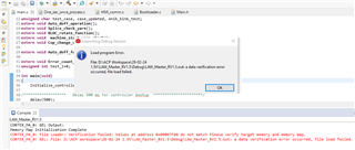
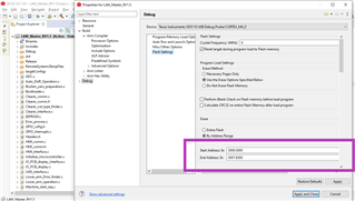
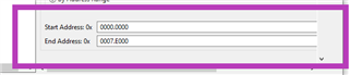
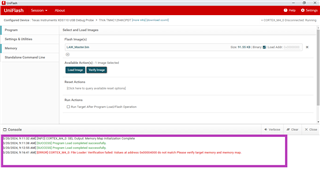
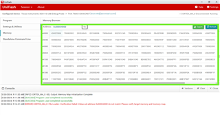
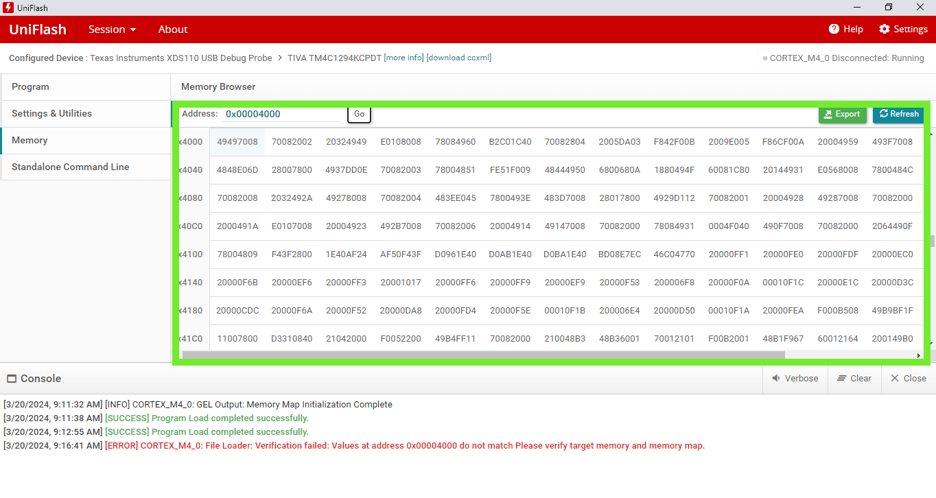
CORTEX_M4_0: File Loader: Verification failed: Values at address 0x00007F80 do not match Please verify target memory and memory map.
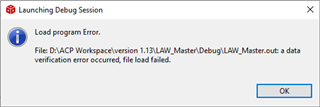
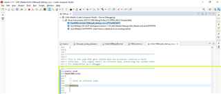
CORTEX_M4_0: GEL: File: D:\ACP Workspace\28-02-24 1.5V\LAW_Master_RV1.5\Debug\LAW_Master_RV1.5.out: a data verification error occurred, file load failed.
How could i find the root cause of this issue. Please resolve this solution as soon as possible.