This thread has been locked.

If you have a related question, please click the "Ask a related question" button in the top right corner. The newly created question will be automatically linked to this question.

CCS/AFE4403: AFE4403 clock settings

Part Number: AFE4403

Tool/software: Code Composer Studio

Hello,

 We are working on a project and we want to use the AFE4403 device. We have noticed in the datasheet that TI recommands to one crystal oscillator if we interface the device with an external mcu (picture below).

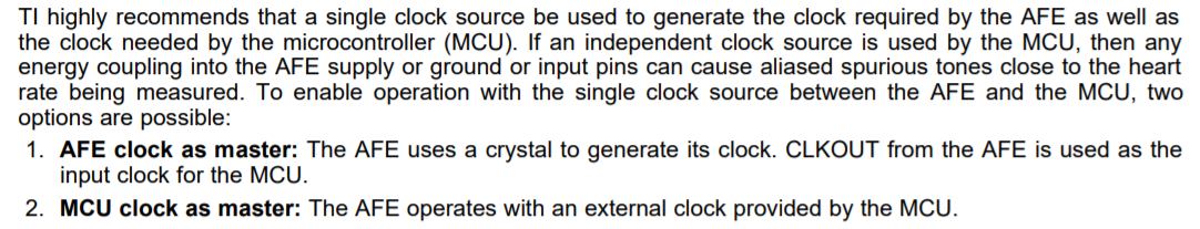
If we are using the second solution (MCU clock as master), then we should connect the clock output of the mcu to the XIN pin of AFE4403 and leave XOUT pin of AFE4403 NC, right ? Or XOUT pin should also be connected ?

Thank you.

Regards,

Mike

  • Hi Mike,

    In external clock mode with an external clock fed in through the XIN pin, XOUT can be left floating.

    The clock signal level can be the same as the receiver supply voltage.

  • Hello Praveen,

    Thank you for your response. If VCM of AFE4403 is not used, could it be left NC ?

    Also we found an example (picture below) on TI website showing that the LED power supply pin of AFE should be connected to three capacitors, and two of them should be polarized one. Is it mandatory to use polarized cap (for 2.2 and 33 uF) for this application ?

    Finally, DIAG_END pin doesn't seem to be really important so it could be left NC, or maybe we're wrong ?

    Thank you.

    Regards,

    Mike