This thread has been locked.

If you have a related question, please click the "Ask a related question" button in the top right corner. The newly created question will be automatically linked to this question.

Compiler: Scheduling data capture

Other Parts Discussed in Thread: ADS54J40

Tool/software: TI C/C++ Compiler

Hi,
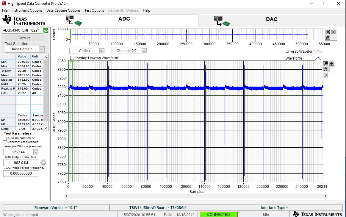
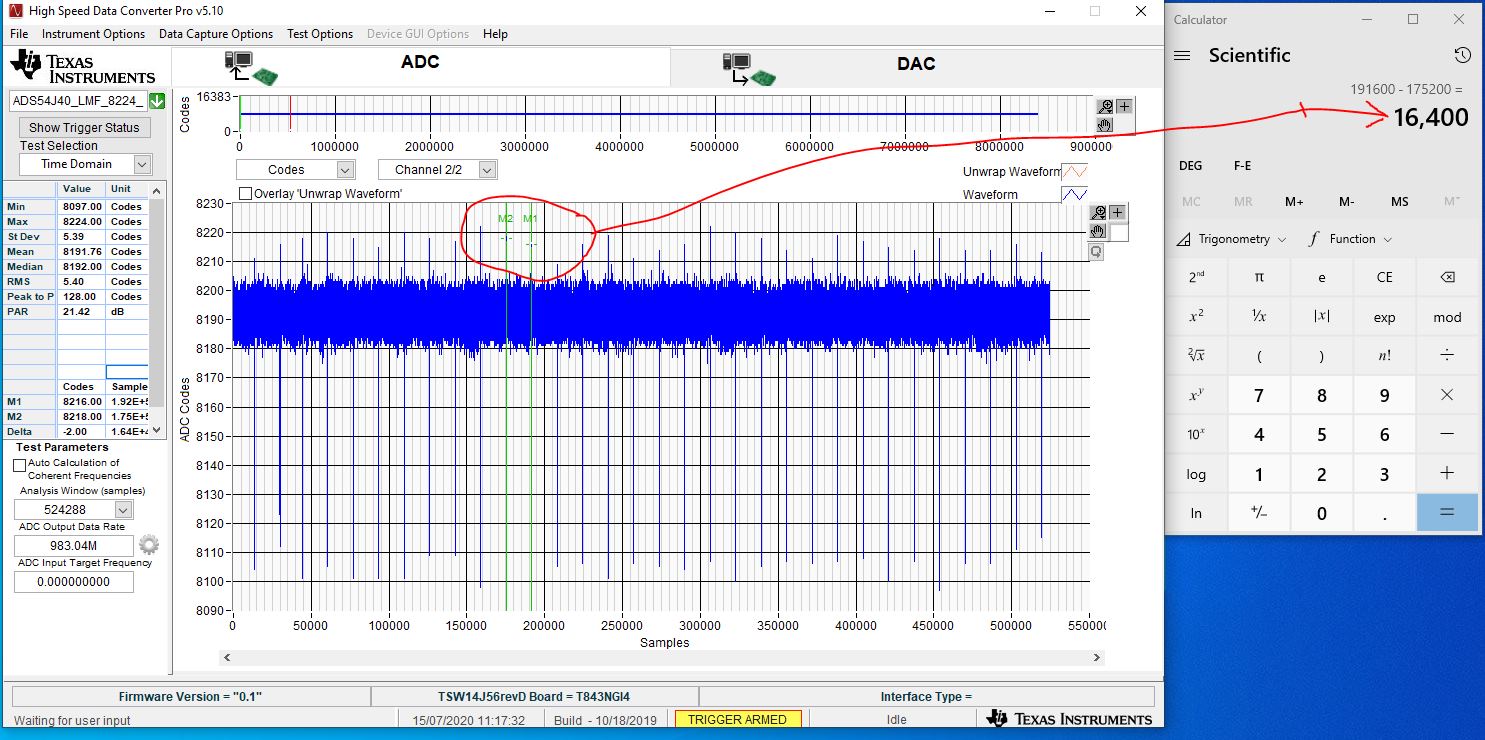
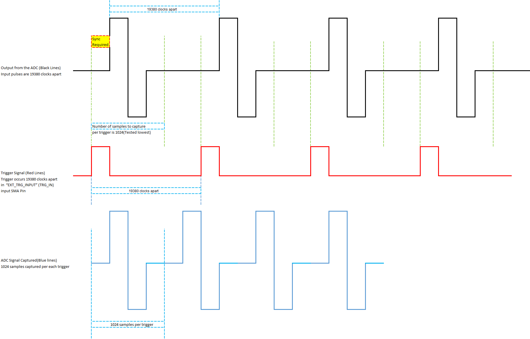
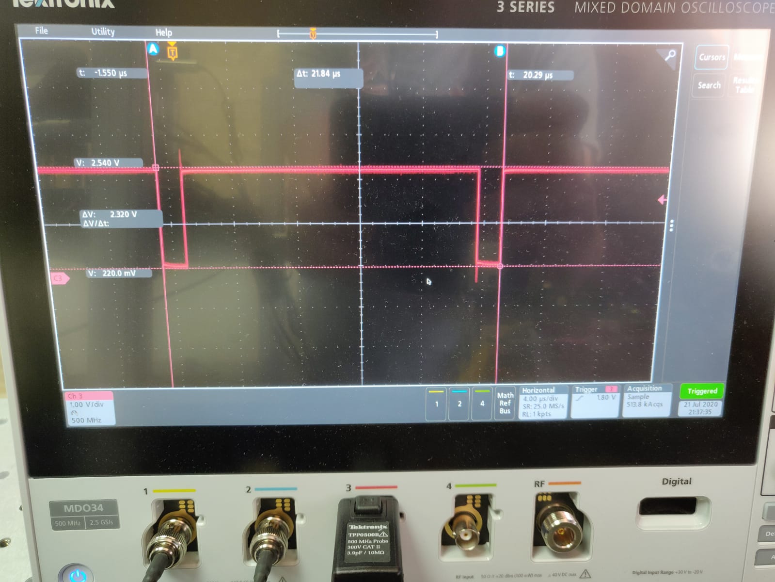
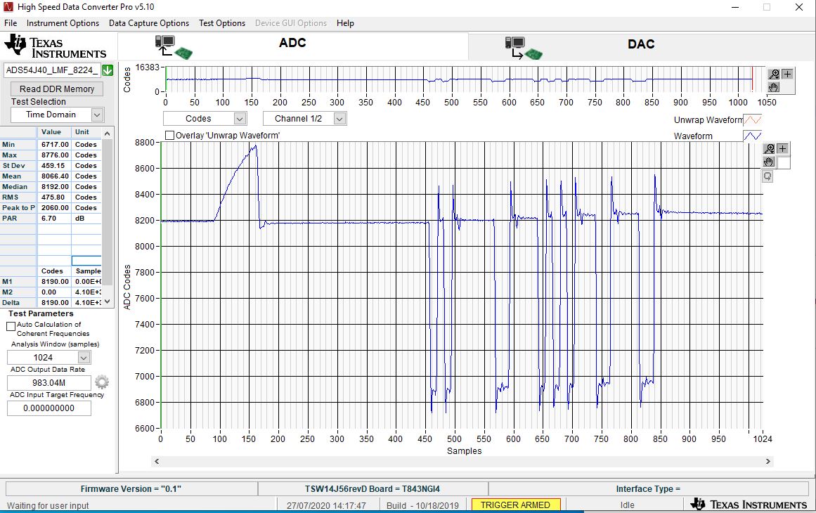
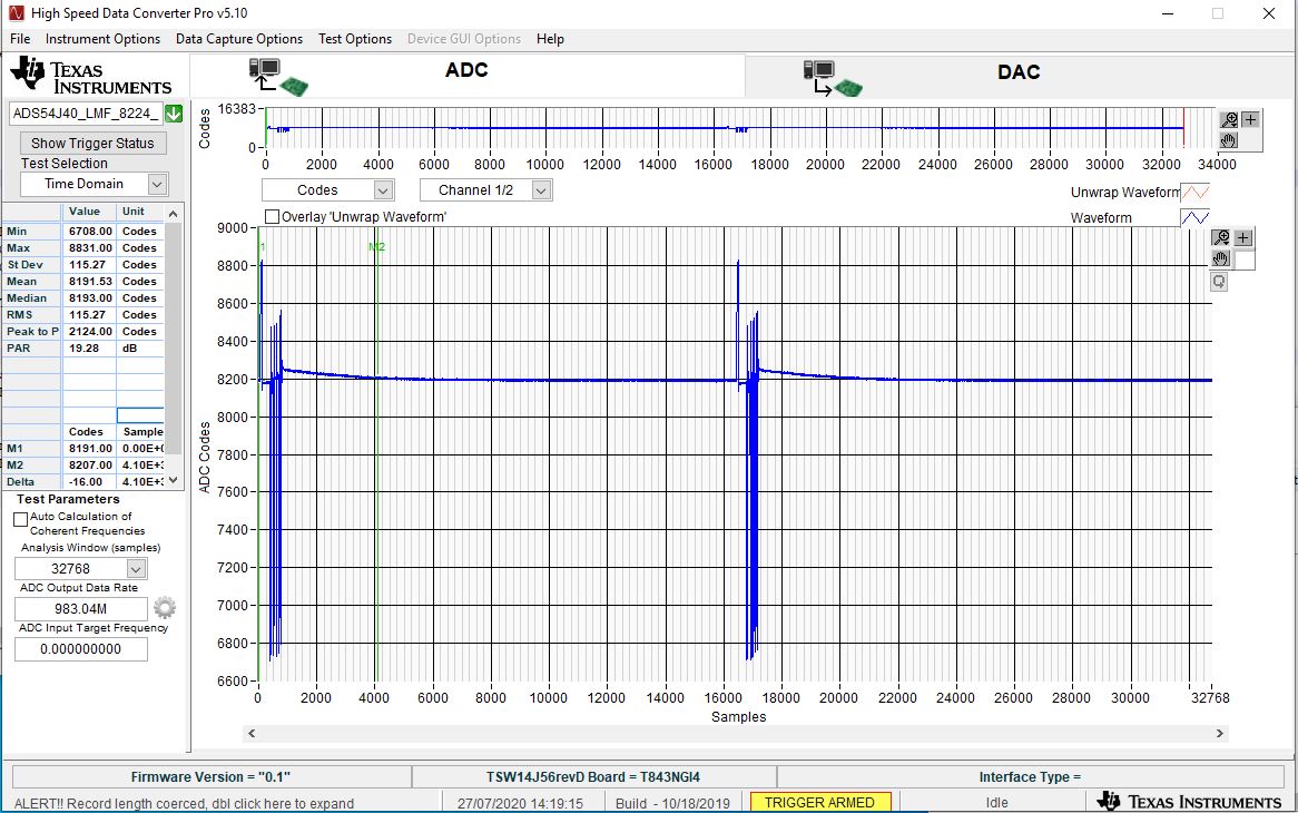
I am using the TSW14J56EVM sampler. The sampler is filled with data retrieved from a photodetector. since the speed of the sampler is a lot faster then the time it takes the photodetector when retrieving the data from the sampler, 98% of the data retrieved is not relevant. My question is there a way to "tell" the sampler when to start when to stop the sampling? I am looking for a way to synchronize my photodetector with my sampler.

Thanks,
Yaron

  • Yaron,

    You may be able to use the external trigger feature of the TSW14J56EVM. Information regarding this can be found in section 3.1.3.3 of the HSDC Pro GUI User's Guide. You may be able use this feature with an automation function. More information regarding the automation features can be found at

    C:\Program Files (86)\Texas Instruments\High Speed Data Converter Pro\HSDCPro Automation DLL

    Regards,

    Jim

  • Jim,

    Is it possible to get an example code that sets the sampler to start every X time for a Y time period?

    When I look at the examples supplied I am no sure how to set these values:

    print "Setting Additional Device Parameters.."
    Err_Status = HSDC_Pro.Set_AdditionalFrequencyParametersForTwoTone(Enable,c_double(ADCOutputDatarate),c_double(InputTargetFrequency),c_double(SecondInputTargetFrequency),c_double(NCO),c_double(Decimation),TimeoutinMs)
    print "Error Status = " + str(Err_Status)

    What is "InputTargetFrequency" or "SecondInputTargetFrequency" ?  X and Y? I am not sure . is there more detailed documentation so I can better understand how this works?

    Thanks,

    Yaron

  • Hi Jim,

    I have found the manual of Automation DLL. I am not sure but I think the way synchronize my sampler to my photodetector is to use the the calibration method:

    int32_t Calibration(char LanesToCalibrate[], int32_t Resolution, int32_t BitErrorValidationTimeInMs, int32_t NumberofLanestoCalibrate, uint32_t AlignDelays[], int32_t CalculatedDelays[], int32_t LanesCalibratedStringLen, char LanesCalibrated[], int32_t TimeoutInMs)


    The first question is this the method to use in order to sync the sampler?

    If it is, additional information will help me to understand how to use it. The manual does not explain in a way I can fully understand the concept. 

    For example, what are the lanes I am calibrating? I know I have two channles, but I am not familiar with the lanes concept.


  • Yaron,

    The calibration stuff is to be used with our LVDS parts. This will not do anything for your case. Please see the attached document and attached example sample trigger code .py file for a possible solution.

    Regards,

    Jim

    Ext Trigger Automation.docx

    from ctypes import *
    import os
    
    '''******************************** Loading the HSDCPro Automation DLL ****************************************************'''
    
    if('PROGRAMFILES(X86)' in os.environ): #selecting the DLL path from HSDC Pro installed location based on 32 bit or 64 bit OS
        dll_path = "C:\\Program Files (x86)\\Texas Instruments\\High Speed Data Converter Pro\\HSDCPro Automation DLL\\32Bit DLL\\HSDCProAutomation.dll"
    else:
        dll_path = "C:\\Program Files\\Texas Instruments\\High Speed Data Converter Pro\\HSDCPro Automation DLL\\32Bit DLL\\HSDCProAutomation.dll"
    HSDC_Pro = cdll.LoadLibrary(dll_path)
    
    '''*************************************************************************************************************************'''
    '''***************************************ADC Configuration Settings********************************************************'''
    '''*************************************************************************************************************************'''
    
    Boardsno = "T843NGI4" #Serial Number of board to be connected. Eg: "TIVHIV9Z" or "TIVHIV9Z-TSW1400"
    Devicename = "ADS54J40_LMF_8224" #ADC device to be selected(should be same as what appears in the HSDC Pro GUI selection drop down box.
    
    Datarate = 50000000 #ADC output Data Rate
    
    numberOfSamplesPerChannel = 65536 #Number of samples per channel has to be specified, based on the operating mode of the ADC (ADC Resolution and ADC Sampling frequency). This will indirectly specifies the Capture period
    
    #Varaible for setting the Trigger Mode
    TriggerModeEnable = 1 #0-Disables the Trigger Mode, 1-Enables the Trigger Mode
    SoftwareTriggerEnable = 0 #0-External Trigger, 1-Software Trigger
    ArmOnNextCaptureButtonPress = 0 #0-Disbale Arm the Trigger for Next Capture,  1-Arm the Trigger for Next Capture
    TriggerCLKDelays = 0 #Specifies the number of Clock delays before trigger
    
    #Varaible for Read DDR Memory
    WaitToCheckTrigger = 1 
    
    
    TimeoutinMs = 30000
    
    '''*************************************************************************************************************************'''
    '''**************************** The actual call to the function contained in the dll ***************************************'''
    '''*************************************************************************************************************************'''
    print "Connecting to board : " + Boardsno
    Err_Status = HSDC_Pro.Connect_Board(Boardsno,TimeoutinMs)
    print "Error Status = " + str(Err_Status)
    
    #Selecting the ADC device.It will automatically download its firmware.
    #Please provide sufficient timeout for completing firmware downlaod operation
    print "Selecting ADC Device : " + Devicename
    Err_Status = HSDC_Pro.Select_ADC_Device(Devicename,120000)
    print "Error Status = " + str(Err_Status)
    
    print "Using HSDC Ready function to check if the GUI is Ready..."
    Err_Status = HSDC_Pro.HSDC_Ready(120000)
    print "Error Status = " + str(Err_Status)
    
    print "Passing ADC Output Data Rate = " + str(Datarate)
    Err_Status = HSDC_Pro.Pass_ADC_Output_Data_Rate(c_double(Datarate),TimeoutinMs)
    print "Error Status = " + str(Err_Status)
    
    print "Setting Number of Samples per channel to capture = " + str(numberOfSamplesPerChannel)
    Err_Status = HSDC_Pro.Set_Number_of_Samples(numberOfSamplesPerChannel,TimeoutinMs)#sets the  Number of samples per channel
    print "Error Status = " + str(Err_Status)
    
    print "Setting Trigger Mode as External Trigger" 
    Err_Status = HSDC_Pro.Trigger_Option(TriggerModeEnable,SoftwareTriggerEnable,ArmOnNextCaptureButtonPress,TriggerCLKDelays,TimeoutinMs)#sets the Trigger Option as External Trigger
    print "Error Status = " + str(Err_Status)
    
    #After Setting the Board for External Trigger mode the Board will wait for High Clock input at EXT_TRG_INPUT (TRG_IN) input SMA Pin and once a High clock cycle is received the Board will start capture till the speciifed amount
    #of samples are captured and then calling the Read_DDR_Memory function will read the captured samples from the Board memory and will load the same to HSDC Pro Software
    #At this point it is expected to give a high clock pulse in EXT_TRG_INPUT (TRG_IN) input SMA Pin to start capturing data
    
    print "Starting Trigger capture.."
    Err_Status = HSDC_Pro.Read_DDR_Memory(WaitToCheckTrigger,TimeoutinMs)#This function will read the captured samples from the Board memory after trigger had occured at EXT_TRG_INPUT (TRG_IN) input SMA Pin and will load the same to HSDC Pro Software
    print "Error Status = " + str(Err_Status)
    
    print "Disconnecting from the board"
    Err_Status = HSDC_Pro.Disconnect_Board(30000)
    print "Error Status = " + str(Err_Status)
    

  • Hi Jim,

    I have tried the python script you have sent me.

    I have changed the "TriggerCLKDelays" and the "WaitToCheckTrigger" to different values and did not see any actual change.

    I am attaching a screenshot, you can see that the pulses detected are about 20,000 clocks between one and the other. What I am trying to do is make the pulses closer. so that in a file with 64,000 samples I will have a lot more then the three pulses I am getting now.

    Thanks,

    Yaron

  • Yaron,

    Try the following points for using the Auto Re-Arm Trigger.

    1.       The Trigger option in the HSDC Pro can be configured as “Auto Re-Arm Trigger” to capture a specified Number of Samples Per channel for each external trigger that occurs at “EXT_TRG_INPUT” (TRG_IN) input SMA Pin. When multiple triggers occur, then the corresponding data that are captured for each trigger will be accumulated in the TSW14J56RevD’s DDR Memory. Once the enough number of captures are performed, all captured data samples from the DDR memory will be loaded into HSDC Pro Software.

    2.       Follow the Steps mentioned in the attached “HSDC Pro - ADC Auto Re-arm Trigger User Flow.pptx” (attached) for setting the TSW14J56RevD board in Auto Re-Arm Trigger mode and capturing the data whenever the trigger occurs. The document also contains the Automation API Functions related to Auto Re-Arm Trigger.

    3.       Add the attached “ADS54J40_LMF_8224_Auto_ReArm.ini” at following location for using this Auto Re-Arm Trigger option. Kindly update the following parameters, if planning to use in some other ADC modes in their respective ADC INIs

    a.       Interface name="TSW14J56REVD_ADC_DDR_DAC_BRAM_256KB_XCVR_FIRMWARE"  à  (Parameter updated, as this Auto Re-Arm Trigger option is supported only in TSW14J56REVD_ADC_DDR_DAC_BRAM_256KB_XCVR_FIRMWARE)

    b.       JESD IP LMFC Realign=1  à (Parameter Added, to add deterministic latency when doing the Auto Re-Arm Trigger)

    Location to add the “ADS54J40_LMF_8224_Auto_ReArm.ini”: C:\Program Files (x86)\Texas Instruments\High Speed Data Converter Pro\14J56revD Details\ADC files

    Regards,

    Jim

    HSDC Pro - ADC Auto Re-arm Trigger User Flow.pptxhttps://e2e.ti.com/cfs-file/__key/communityserver-discussions-components-files/81/ADS54J40_5F00_LMF_5F00_8224_5F00_Auto_5F00_ReArm.ini

  • Hi Jim,

    First of all, thank you for the detailed explanation.

    I have followed your instructions and started working with the new firmware today.

    I have played with the parameters "Number of samples" ,  "Number of triggers" and "Trigger delay" all day. I Have tried the different combinations with or without delay.

    I did manage to see a difference, in some of the combinations there were more pulses recorded but not dramatically, instead of a pulse every 20,000 clocks, I saw two pulses near one another (5000 clocks apart) and then 20000 clocks after one pulse and then again 20,000 clocks after two pulses and so on.

    Can you give a combination of parameters that I can try that will improve the density of the pulses?

    Or any other idea to try will be welcomed 

    Thanks,

    Yaron

  • Hi Jim,

    We have run a few more tests, we do see a small difference. our pulse rate is 19600 clocks, in normal capture will get a pulse every 19,600 (I have attached a screenshot). This means that we need the trigger to be activated after a smaller number of samples. The smallest number of samples the system lets you select now is 4096 samples. We have taken some samples when the sample rate was 4096,8192,16384 and got the same results each time, the pulses were now 16384 apart from one another, this is an improvement but still, there too much of empty data being a recorder. if it is possible to reduce the sample rate below 4096 we might be able to get a better density.

    I am attaching all screenshots from our tests, maybe it can help better understand our problem.

    Thanks,

    Yaron

  • Yaron,

    See attached.

    Regards,

    Jim

    1.docx

  • Hi Jim, 

    I have tried the parameter but I am not getting the correct results.

    I have run the following test:

    1. Our pulses are 19380 clocks apart from one another if the sample rate is 64k you will expect 4 pulses to be found.
    2. I have set the sample rate to 64k and the number of triggers to 2
    3.  I got the correct results (Attached): 8 pulses found and 4 for each trigger, the fourth pulse is near the fifth 

    This means that the second trigger narrowed the distance between two pulses.

    Second test:

    I am trying to narrow the distance between all pulses. since a pulse length is around 2k clocks, using the same logic, I have set the sample rate to 4k expecting that each trigger will catch one pulse and immediately after another trigger will be activated cathing the next. In this way, I expected to close the gaps between the pulses.

     I am attaching the results of the second test with 4k sample rate and 64 triggers. you can see that the size of the gap between the pulses remained the same. I have also tried with a smaller sample rate down to 1K with the same results.

  • Yaron,

    In order to reduce the width between the pulses, please try to capture single pulse for each trigger that occurs at “EXT_TRG_INPUT” (TRG_IN) input SMA Pin. To do that we have to produce the trigger signals at the SMA pin, right before every pulse signal that you are targeting to capture as shown in the attached image, so that for every trigger you will capture 1024 samples(“Number of Samples Per Channel” set in the “Capture Option” Menu) which will include the pulse data.


    Regards,

    Jim

  • Hi Jim

    I could be missing something, but that exactly what I was trying to do.

    When I capture 2048/1048 sample I see one pulse. I have set the triggers to trigger multiple times while the number of samples is 1024/2048, but I am getting the pulse density like before when I was working with a larger sample size.

    What am I doing wrong?

    Please see attached video

  • Yaron,

    Can you send a scope shot of the external trigger signal at U29 pin 8?

    Regards,

    Jim

  • Hi Jim

    Scope images are attached

  • Is this at U29 pin 8?

  • Yaron,

    The software teams response to your scope shots:

    We observe that, the time period between the ADC captured pulses (calculated as given below) and the time period between the Trigger Pulses given to SMA Pins are closer to each other. We think, these two signals have to be properly synchronized such that the trigger pulses occur just before the input pulses. Other than this, we don’t see any obvious issues.


    Calculated Time period between the ADC captured Pulses = 19.714355us (based on the customer’s inputs, Sampling frequency = 983.04MHz, and Number of Samples between the Consecutive pulses = 19380)


    Regards,

    Jim

  • Jim,

    The timing measurements were not supplied accurately, only a rough measure to give the general idea of timing.

    Basically the trigger on the SMA connector actually is the trigger to the laser system which in turn generates the analog signal sampled by the ADC. 

    In our tests, if we supplied the number of samples to acquire as 16384 it looks like working. Tried lower values: 8192 down to 1024 (in multiples of 1024 power of 2) we still get the grabs of the signal 16384 distance apart. 

    This is the main issue currently we encounter. 

    Thanks,

    Yaron,

    P.S 

    Is there a new version of the Pro Data convertor, a few weeks ago, you said it is going to be out in a month.

  • Yarron,

    We think the issue is the trigger pulses are not occurring right before the input pulses of the ADC, which is why you are not able to capture the required pulse samples from the ADC.

    The next version of HSDC Pro is not going to help with this issue. The release date slipped. We are trying to get it released by the end of this month.

    Regards,

    Jim  

  • Did you test it working down to 1024 samples with an external trigger?

    What was the trigger frequency?

  • Yaron,

    We think, the issue is the trigger pulses are not occurring right before the input pulses of the ADC, which is why you are not able to capture the required pulse samples from the ADC.

    Regards,

    Jim

  • We did not test this.

  • Hi Jim,

    Is it possible to test this in your environment?  If you will see what we are seeing here, it might lead to a bug in the system that needst o be fixed.

    Thanks,

    Yaron

  • Yaron,

    We are having very limited time in the lab right now. I will try to set this up but it may take some time.

    Have you tried to trigger the pulses right before the input pulses arrive to the ADC?

    Regards,

    Jim

  • Hi Jim.

    Yes, we have moved our synthetic pulse and now it display before the trigger, you can see its length is less than 1000 clocks.

    The minimum distance between the pulses remains the same around 16380 clocks. we have tried with a different numbers of samples (1024,2048,4096,8192).

    It looks like something is blocking the number of triggers at your side.

    Thanks,

    Yaron

  • Yaron,

    We will attempt to set this up in the lab but it may take a few days before we have any new information.

    Regards,

    Jim

  • Yaron,

    This has been delayed due to many other activities that have come up. We did start setting up the hardware today. Hopefully the software team can start working on it early next week.

    Regards,

    Jim

  • Thanks, 

    Hope to hear from you soon on this issue.

    We are struggling with this problem for weeks now.

  • Yaron,

    We have duplicated your issue in the lab and trying to see if changes can be made to the software to accomplish what you need. If this is a firmware issue, we will be unable to help you as we no longer have firmware support. More info to follow.

    Regards,

    Jim 

  • Yaron,

    We have duplicated this issue and this will require a firmware change that we cannot support at this time due to lack of resources.

    Regards,

    Jim