


Hello,
I was checking the LLC design and some doubts araised regarding the resonant network.
The specification for minimum bulk voltage at the LLC input is 250V. Then, the calculations show that the gain needs to be 1.542 at this operating point. In addition, the design note adds a margin of 1.1 increasing the gain to 1.697.
However, the resonant network selected is Lr=27uH, Cr=94nF, Lm=240uH. This cannot deliver full power when input voltage is at the minimum (250V). Using fisrt harmonic approximation is clear because at minimum switching frequency the gain is only 1.13 (at full power). The converter would enter in the capacitive region with a gain lower than 1.697.
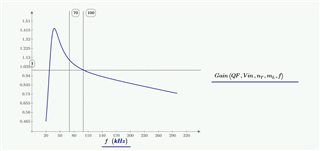
Simulations show higher gain at 70kHz but anyway far of the necessary gain.
I guess the design considers the LLC cannot deliver full power at 250V input but then, the design guide should be clear to show that the mecessary gain calculated is not used for the resonant network calculations.
Please, could anyone clarify it?
Thanks
Jesús
