This thread has been locked.

If you have a related question, please click the "Ask a related question" button in the top right corner. The newly created question will be automatically linked to this question.

TIDA-03031: Power backup solution for 70W application

Part Number: TIDA-03031
Other Parts Discussed in Thread: LM5160, TPS2660, TPS2663, LM5146, LM5145, LM76005, TPS54561

Hi Sir,

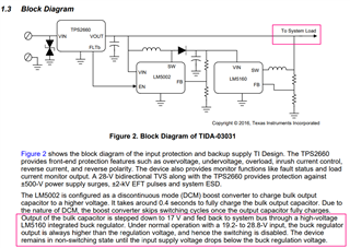
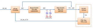
We would like use TIDA-03031 design in a 70W application.

Would you help recommend another bulk regulator solution?

LM5160 and TPS2660 have 2A output max only that don't meet requirement.

Thank you

Amos.

  • Hi Amos,

    Please consider TPS2663 for high current designs.

    Can you share details of your system and product 

    Best regards,

    Rakesh 

  • Hi Rakesh

    Our product is a x86 base PAC system, following is the simple block diagram. 

    The first DC/DC stage provide the 12V main power  for systam.

    If PAC system received 24_Vin_FLT#, system start memory backup and system shutdown process.

    Would you help recommend the 48V to 17V@5A bulk DC/DC solution? LM5160 has only 2A output max.

    Thank you

    Amos.

  • Hi Amos,

    Thanks for the details.

    I have assigned this thread to the team who can help on buck converter solutions. The appropriate engineer will get back to you.

    Best Regards, Rakesh

  • Hi Amos,

    Take a look at the LM5145 as a controller solution. You can use 60V FETs for a 48V input. Take a look at the 12V design example in the datsheet and also the LM5146 EVM (12V/8A/400kHz).

    Another option is the LM76005 60V/5A converter (with integrated FETs). However, this depends on ambient temp and airflow conditions -- the controller solution is generally more favorable than a converter from a thermal standpoint.

    Regards,

    Tim

  • Hi Tim

    Are both LM5145 and LM76005 disabled in output OVP condition and auto restart when OVP condition cleared?

    Thank you

    Amos 

  • Hi Amos,

    If the FB voltage goes high, the loop responds to pull VOUT lower by turning on the low-side FET as needed.

    Regards,

    Tim

  • Hi Tim

    If the LM5145 OVP protect behavior is turning on low-side MOS, seems TPS2660 (eFuse) output (24V) will short to GND thru the buck low-side MOS in normal operation?

    Does LM5145 and LM5160 have the same OVP behaviors? 

    I found another solution TPS54561, the OVP behavior is turning off high-side MOS. Is low-side MOS turning off, too?

    TPS54561 OVP => When the OVP comparator is activated, the high side MOSFET is turned off and remains off until the output voltage is less than 106% of the desired output voltage.

    Thank you

    Amos

  • The TPS54561 is a non-synchronous converter with a diode instead of the low-side FET, so it has no means to actively pulldown the output.

    Note the output is not directly pulled low if the low-side FET is on, as the buck inductor is in series.

    Regards,

    Tim

  • Hi Tim

    TIDA-03031: Under normal operation with a 19.2- to 28.8-V input, the buck regulator output is always higher than the regulation voltage, and hence the switching is disabled.

    Does LM5160 "switching is disabled" means both high/low side MOS turn off?

    We are worried about any impact if we replaced LM5160 by different buck regulator in TIDA-03031 reference design.

    For  LM5145 and LM76005, your mention is 

    "If the FB voltage goes high, the loop responds to pull VOUT lower by turning on the low-side FET as needed."

    Does the external voltage source (24V) cause LM5145 and LM76005 low side MOS damaged? If FB voltage always goes high and low-side MOS is  always turning on.


    For TPS54561:

    TPS54561 includes a MOS and a diodes between SW and GND. Is it used for output voltage discharge once over voltage occur?

    Our concern is the external higher voltage source (24V) tie to TPS54561 output may cause the MOS and diodes damaged. Or there has a current leakage thru MOS and diodes.

  • Hi Amos,

    Yes, "switching disabled" generally means both FETs are off.

    If the loop responds to an output OVP, the power stage should be protected by negative current limit. Please verify operation in your application using the applicable EVM.

    Regards,

    Tim