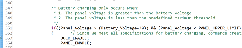
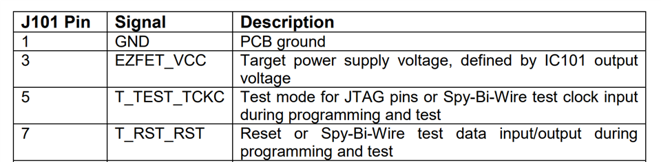
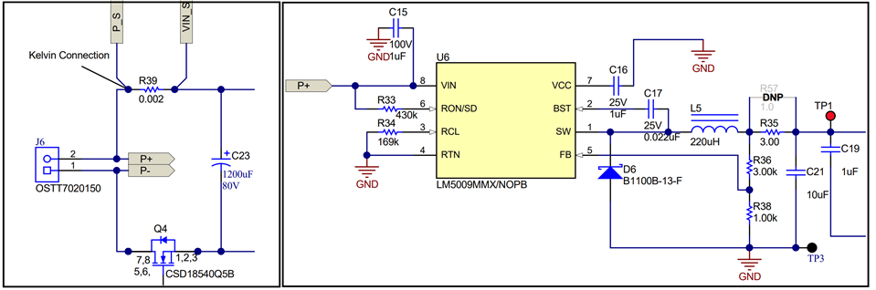
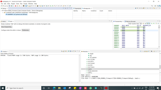
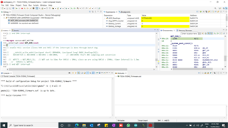
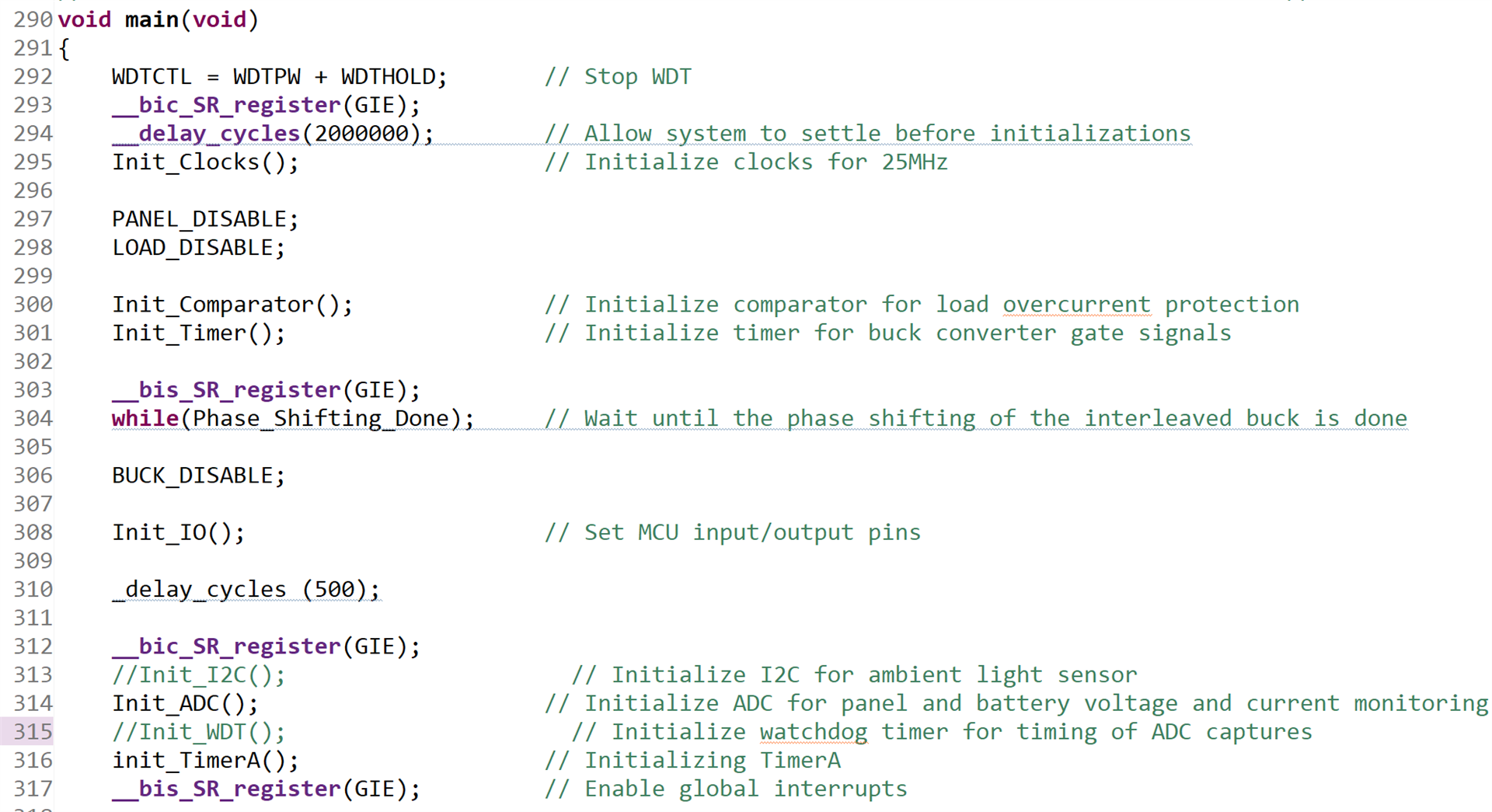
This thread has been locked.
If you have a related question, please click the "Ask a related question" button in the top right corner. The newly created question will be automatically linked to this question.
I programmed the required firmware. but the fabricated device is not functioning. kindly suggest a solution.
can any one come provide live solution so that i can finish my work.
thank you.
Hi Kameswara,
I need a little more information here, to help you with this problem.
You did copy the design files from TI.com and rebuild a board, correct?
Does the board power up correctly? Do you have 10V at TP1 and 3.3V at TP2?
If this is working the next step is to debug the software. Did you use the MSP-FET tool to program the board?
Best regards,
Andreas
hi sir,
Yes i designed the PCB fro the files given from TIDA010042.
power up i did but still having doubt . the desgin guide provided with TIDA 010042 is not clear.
i usedMSP430f5229lp ezfet lite simulator to connect to main controller in TIDA 010042.
when i connect 2 pins 2 and 3 in J2 in the tida 010042 bard and i get 3.3v.
but i never get 10 v at tp1 how will get?
May be i am not doing in a correct way.
Hi Kameswara,
Okay, so the 10V are generated from the input voltage of the solar panel.
You can simulate this by connection a power supply with 15V to 22V to the input connector J6. Then you also need to connect battery or load to J5. With this setup you should see that the system is working. Please follow the test setup described in the Design Guide under 3.2.1.
Best regards,
Andreas
Yes sir i did that. I connected electronic load under CV mode as CC mode is not suitable mentioned by another TI expert. but when i connected the input am not getting 12v at battery junction nor load junction sir.
Hi Kameswara,
Okay, do you get any voltage at the output connectors or is it reading 0V?
If you get no voltage at all. I think the software is shutting down the system. Can you start the software in debugging mode and check if the code reaches line 353, by setting a breakpoint there?
Best regards,
Andreas
Hi sir,
I am getting 0 v at output voltage terminal.
right now my board is in my lab tomorrow morning i will check the code.
I did run the code earlier but i am not sure whether its working or not so meanwhile if it possible can you share some user guide or procedure to load the firmware in ccs and steps to flashing in TIDA 010042 for stand alone use.
my mail id is oks1988@gmail.com.
thanks you sir.
Hi Kameswara,
First you need to download the TIDA-010042 Firmware and import it into CCS.(Project->Import CCS Project-> select downloaded folder)
Afterwards you need to connect the required signals from the debugger you are using to the connector J4 of the TIDA-010042 board:
TIDA-010042 pins:
MSP430f5229lp ezfet lite simulator pins:
Now you should be able to hit the debug button in the CCs project and program the device.
Best regards,
Andreas
thanks for the info sir. I did the same. Now i cleared of confusion. tomorrow i will debug and check the code as you stated sir.
Hi Kameswara,
This is normal behavior, there is a default breakpoint at the beginning of the main() function.
If you press the green run button it should continue. You can add another break point in line 353 I showed earlier by double clicking on the left border of the code window and see if you reach the code where the Panel and the Buck is enabled. As an alternative you can use the single step options to step over the code line by line and observe what the SW is doing.
Best regards,
Andreas
Hi Kameswara,
that a good sign, now you need to insert breakpoints at the important parts of the code to see what the software is doing. The first question is if it is enabling the panel and the buck converter.
Best regards,
Andreas
sorry to ask this ... i underestand from code that buck is enabled when it satisfies the line if panel volatage is > than battery voltage right? i have electronic load connected as CV source to batery with supply . should i need to connect real battery fo this process so that buck is enabled? or with out connecting the sofrware will check. because till now after resuming the debug the program is still running and never stoped.
wt to do?
Hi Kameswara,
That is correct the buck will only be enabled it the input voltage connected to J6 is greater than the voltage at the battery connector. So you need to connect a power supply with at leas 15V to J6 and a electric load set to 12V to the battery connector.
You can stop the software at every point by inserting a breakpoint and check the voltages the system is reading for battery or panel voltage.
How to do this is described here in chapter 7 of the Code composer studio user's guide: https://software-dl.ti.com/ccs/esd/documents/users_guide/index_debug.html
Best regards,
Andreas
Hi sir,
I did and buck is enabled. But, after that no change its still running and at one pont it came out.
Hi Kameswara,
Okay, this screen means there was some kind of exception triggered in the code.
Do you have the 10V at TP1 by now? Without this rail the design will not work.
Best regards,
Andreas
Hi Kameswara,
Okay, that explains why it is not working.
Can you check the input voltage at the LM5009 (Pin 8 of U6)? This should be the same voltage as the panel voltage you connect to pin 2 of J6 Which has to be between 15 and 22V.
If this is correct please check the feedback voltage divider R36 and R38.
Best regards,
Andreas
Hi sir am getting this issue. no symbols defined and getting suspend HW breakpoint
Hi Kameswara,
Did you get the 10V Rail working?
Your problem looks like it is caused by an unhandled Watchdog timer interrupt.
Can you try commenting out the Init_WDT() function in line 315 like this:
Best regards,
Andreas
I tried commenting line 315 but same response sir.
10 V at TP1 is not coming sir. is this related to code to make the voltage to reflect at TP1 or without any code TP1 should show 10v sir. because now code not even reach buck enable / panel enable
Hi Kameswara,
I am not the original author of this design, but in my understanding there should be 10V at TP1 before the Software starts running. Since the 10V are necessary to supply the gate drivers to enable and disable the buck, the panel or the load.
So without the 10V it is not possible to enable or disable anything. Can you check the input voltage between Pin 8 and Pin 4 of U6 (The LM5009).
If this is not helping i have to setup this board myself in the Laboratory. But this will take until next week.
You can also try removing the initial PANEL_DISABLE call in line 297 and see if this helps.
Best regards,
Andreas
HI sir,
I checked voltage between pin 8 and pin 4 it was 20v (I set the RPS at 20v as solar source) but output of the LM5009 is only like 1.9 v i check the r36 and r38 both are correct value as well.
dono Y LM5009 is not giving 10v....
I commeted line 297 and 315 as well but same behaviour.
Hi Kameswara,
In this case this is a hardware related problem at the LM5009. This means we can disregard software for now since it does not impact the LM5009 behavior.
You could check the other voltages and waveforms on the pins of the LM5009 and compare them to the TINA-TI simulation model you can find on the product page of the LM5009. This model can be easily adjusted to the circuit used in TIDA-010042.
Another option is to replace the LM5009 and see if the IC is just broken.
Best regards,
Andreas
I think let me give eternally 10v by bypassing LM5009 through TP1 adn check the board and software sir.
i would like to write you personal email to you is it k for you? can u send me test mail to oks1988@gmail.com So that I can ask about few things.