This thread has been locked.

If you have a related question, please click the "Ask a related question" button in the top right corner. The newly created question will be automatically linked to this question.

TINA-TI: Iso-Forward circuit with UCC28C40

Part Number: TINA-TI
Other Parts Discussed in Thread: UCC28C40, UCC28C42, UCC28C43, PMP30720, TL431

Hello E2E,

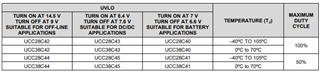
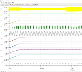
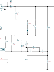
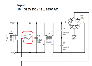
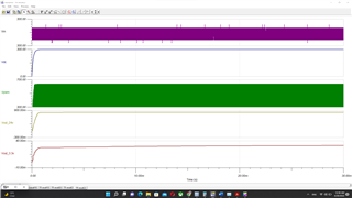
I used WEBENCH® Power Designer to design an flyback power supply and I selected UCC28C40 PMW controller circuit but before I order the component I want to simulate this circuit using TINA TI to see the real outputs and also to optimize the circuit before manufacturer it.

Here is the circuit link from WEBENCH® Power Designer

https://webench.ti.com/appinfo/webench/scripts/SDP.cgi?ID=6EF06136D7B197F9

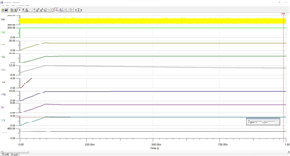
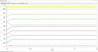
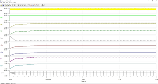
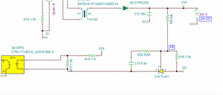
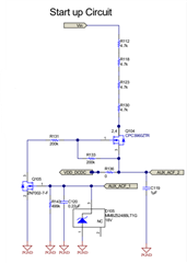
I want to have multiple outputs on the circuit for that I modifieded the circuit on WEBENCH and I took the values of Npr and Nsec of the transformer and I used them in my design but I can not take correct outputs, so may you please check my circuit and modify it to make it work.

I am not sure did I used the correct transformer and optocoupler or not please guide me and modified the circuit .

My circuit TSC file is attached.

Sincerely,

Abdelrahman

UCC28C40.TSC

  • Hello Abdelrahman,

    Troubleshooting a design/simulation can be time consuming.  I will take a look at the simulation file and get back to you next week with recommendations.

    Regards,

    Eric

  • Thank you , I'm looking forward for your answer as fast as you can please.

    Sincerely,

    Abdelrahman

  • OK.  Early next week...

  • Hello again

    I took a quick look at lunchtime.  I think the transformer models are incorrect.  There is no model for a multi-turn transformer but you can create one.  First, create a netlist with the transformer pins and parameters (.LIB file).  Then, create a symbol in TINA and incorporate the netlist.  I found this information in a similar E2E post.

    https://e2e.ti.com/support/tools/simulation-hardware-system-design-tools-group/sim-hw-system-design/f/simulation-hardware-system-design-tools-forum/765959/tina-spice-tina-ti-how-to-create-power-component-model-in-tina

    Eric

  • Thank you for your answer, 

    İ tried before the method you mentioned and I think I checked many posts on E2E but I couldn't make it working .

    May you please make the transformer correctly 

  • Hi Abdelrahman,

    Doing the work to model the transformer for you is beyond the scope of E2E support.  Go through the TINA training modules and re-examine the thread I identified.  I think it will start to look easier to you.  TINA Video Training Modules.

    Regards,

    Eric

  • Thank you Mr. Eric your answer helped me a lot,

    I was able to use the normal transformers from tina and I created the schematic and simulate it correctly.

    To get the correct value I used some diode and cap from TI ref designs to get the circuit working

    This circuit should work with wide range of DC or AC input, and I already test it with 300 DC input, and I take correct values as below


    But when I test it with input of 40 DC or 100 DC, I am taking some ripple on the outputs

    (For 100 DC input)


    (For 40 DC input)


    Also, I noticed that the VDD of the PWM controller which I feed it with 15v dc is not stable and the voltage is decreasing may you explain to me why that it happines ?

    As well , before I draw the PCB of the schematic I should be most grateful if you would review the completely schematic if any components are missing or if i need to add anything else.

    I am looking forward for your answer and your reviewing sir.

    Zaim.

    UCC28C40-viper37_FB.TSC

  • The AUX output looks like it is cycling between the STOP (6.6V)V and START (7.0V) thresholds of the UCC28C40.  Also, when VDD drops below the Stop threshold the PWM gate output stops too.

    1) This is probably happening because R5 is too high (37.4k).  I'm quite certain you need to reduce this to 10's or 100's of ohms.

    2) Why use the UCC28C40?  The Start/Stop thresholds are very close together.  Can you switch to the UCC28C43 (7.6V/8.4V) or UCC28C42 (9..5V/14.5V) to have a wider operating range?

    Regards,

    Eric

  • Thank you for your response, Mr. Eric,

    The reason of using UCC2840 IC is because WEBENCH recommended it but according to UCC28C42 datasheet and your recommendation UCC28C42 will be the best PWM controller for my application for that I used it on my circuit, and i changed the R5 value with 10ohm and it worked decreased the voltage and now the start/stop thresholds are between 9vto15v.

    I simulate the circuit again with these modifications with 100dc input and the results as shown below 

    the results looks well only I have 4 questions left

    1st. when I check the outputs of 5v I got 6v and for 3.3v I got 4v , these 2 supply source will be used for supplying FPGA and MPU..etc for that how can i get the exact values for them ?

    2.st In the feedback circuit as you see I took the feedback from only 24v supply source and i used different circuit that used on WEBENC


    Webench feedback circuit 


    The feedback circuit I used

    The feedback circuit I used

    also, as you see the circuit it works on TINA TI without any problem, but I am worried about building this circuit on real PCB, which circuit should I use to make the power supply compact with high efficiency?


    3rd. The power supply should works for AC and DC input for that I am not sure about which fuse should use because when i check many AC DC converter reference designs from TI i found that they are using AC fuse but when i search on the internet I found some people saying when AC and DC input are applied DC fuse will be better if used , so which one it better for this circuit ?
    Therefore, I noticed that the PMP30720 reference design uses the UCC28C42 too but when I checked to the schematic of it I realized that it there are many components (cap….etc.) are used there but Webench did not recommended it like this part below

    should I do the same also for my circuit?


    -4th. Should I use the varistors on the input of the circuit like this circiut input below ?

    I apologize for such a long writing, and I am looking forward for your answer.

    Sincerely,

    ZAIM.

  • Hi Zaim,

    1) The PWM control is not regulating.  The AUX voltage should be DC, not oscillating between 9V and 15V.  You did not increase the capacitance on the VCC pin.  It's still <5uF.  Is the error amplifier output constant, or swinging from high to low?

    2) The Webench recommendation is probably the safest approach.  It has an LDO (Q1 and DZ) to protect the opto and TL431.

    3) The Webench circuit is the simplest implementation.  The PMP30702 includes Q105 to shut off the HV startup current (via Q104) to have the best efficiency.

    4) The varistor protects against high voltage surges.  For your first (lab only) prototype you probably don't need it.  For a circuit that's going to be used in high volume application it should be included.

    Eric

  • Thank you for your assistance with this matters  ,I am so very grateful for your time.

    Sincerely,

    ZAIM.