This thread has been locked.

If you have a related question, please click the "Ask a related question" button in the top right corner. The newly created question will be automatically linked to this question.

TIDA-010038: Extension of output voltage range

Part Number: TIDA-010038

Dear Support,

We are trying to implement the TIDA-010038 reference design with some modifications; the main one is having a temperature dependent output voltage. The voltage range required is 26.5V to 29.5V (temperature optimized battery charger). Unfortunately we have some stability issues. The stability issues come in effect when starting up close to the top of our voltage range (>28.4V without load and >27.4 with 4A load). The system also falls into instability (after a successful startup) when the output voltage reaches approx. 29V, with or without load.

So far we have experimented (with no success) with the following:
- we have deactivated the constant current functionality (R30 open and U6B.pin6 tied to ground).
- we have added a second 22nF capacitor, from Q2.pin4 to C13/T1.pin3 (split capacitor configuration as discussed in another forum thread).

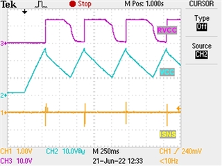
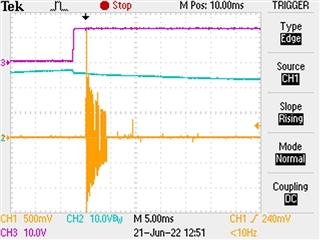
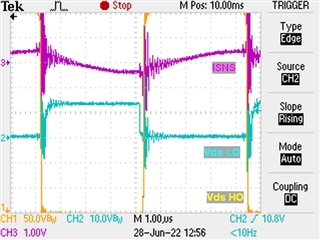
We attached a number of screenshots from our oscilloscope. Some present our circuit in normal operation, and some illustrate the issues we have. In the screenshots we show the voltage output, the output of the current sense amplifier (whose pin is only feeding the scope, not the power supply circuit) and a magnetic pickup on top of the transformer.

Could you suggest any further tests / improvements or ideas as to the root cause and fix for our issue ?
Are there any specific measurements that could help us better understand our problem?

Best Regards,
Pantelis

24Vout with ~3.5A load (working stable)

27Vout with ~4A load (working stable)

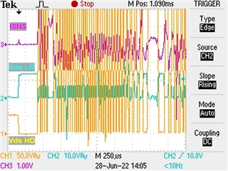
28Vout with ~4A load, pickup on transformer (fails to start up)

29Vout, without load, pickup on transformer (fails to start up)

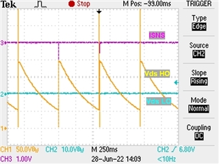
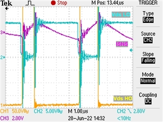
Detailed view: 29Vout, with 4A load, pickup on transformer (fails to start up), the glitch can be ignored.

  • Hi,

    We need sometime to learn your problem and waveforms.

    Before we provide any solution, I suggest you check/capture the Vcc, RVcc, and Isen to see whether OVP, UVP, or OCP is triggerred.

  • Ok, we will check and capture the waveforms you suggested. An important note we forgot: We implemented the design using UCC256404, not UCC256301, due to availability. But we were informed that it is pin-to-pin and functionally equivalent so we proceeded. Thank you!

  • Hi,

    The failed wave seems like the hiccup, you can check whether the hiccup frequency is same as you set and then check which signal trigger the protection   

  • Hello all,

    We are back with some waveforms from the relevant signals:

    In case they are not clear, the max voltages are Vcc: 27.2V, RVcc:13.6V and 560 mS period.

    Here is a close-up of the ISNS pin:

    We are not sure what you mean by "hiccup frequency". If you mean the restart time after the fault, isn't it fixed at 1 second? We tried to find how to reprogram the restart frequency in the datasheet and the design guide, but we couldn't locate it. Could you point us to the right direction please?

    Best Regards,

    Pantelis

  • It seems you triggered OCP2 (average fault with 2ms timer), means too large startup current.

    What have you changed from TIDA-010038?

  • The most important changes we made (that we can think of) are:

    1) We changed the following parts
    - From UCC256301 to UCC256404
    - From CSD19533Q5A to IRFH5010TRPBF
    (because we couldn't find them anywhere to buy)

    2) We changed the voltage divider (R40, R41 and the rest) to produce a higher output voltage.
    3) We have deactivated the constant current functionality (R30 open and U6B.pin6 tied to ground).
    4) We have added a second 22nF capacitor, from Q2.pin4 to C13/T1.pin3 (split capacitor configuration as discussed in another forum thread)

    The rest of the components are either the ones listed in the original BOM or equivalents.

    Is there a chance our issue is related to our selection of the SR mosfet?

  • Hi Pentelis,

    I see the key message, "you increased the output voltage". This will introduce a lot of issues, such as the LLC Gain ability, aux winding voltage for Vcc.

    Can you change them back and check your transformer in first?

  • Hello Desheng,

    We tested first at the nominal voltage (24V) before making any changes and it worked properly.

  • If so, you need increase the secondary winding by 1~2 turns.

  • A change to the transformer is something that we would wish to avoid, until we can't do otherwise. Do we have any other options to explore?

    Right now, we have trouble starting it at around 27V with a 4A resistive load attached. The design guide says that the supply has a tunable range of 22 to 28V. Is the design guide mistaken? Are there any other limitations that we are unaware of or didn't consider?

    As a different route, if we limit our desired output to 28V, could we make it work reliably without a change of the transformer? If yes, what would it take?

  • Hi Pantelis,

    Maybe the original designer haven't carefully check this corner condition's startup. Let's fix it now.

    First, please check how is the primary resonant current and Vds of MOSFET during 27V4A startup, I am thinking the LLC may enter CAP zone and lose ZVS, this should be avoid. If so, you must need to adjust the resonant tank or transformer.

    Then, let's slow down the startup slope, and reduce the primary startup current, to avoid it trigger the OCP2 during softstart.

  • Hello Desheng,

    Thank you for the pointers, we are looking into taking the measurements you asked.

    In the meantime, we noticed something in the TIDA-010038 design guide. In page 12, equation (27) the result for Lm is 450uH, rounded up to the standard 480uH in equation (30). Then, in equations (33) and in paragraph 2.3.2.19 the value of Lm becomes 408uH. The transformer in the BOM has a primary inductance of 400uH and that is what we used. Is this a mistake or we misunderstand something? Could this be affecting our situation?

    Also, the calculated turns ratio is 8.25 but for all the equations 8.5 is used. That change is indeed mentioned in the guide, but could that little rounding affect our marginal case in a negative way?

    We will report back with our measurements of the resonant current and Vds.

    Thank you and best regards,
    Pantelis

  • The transformer datasheet is attached below, it should be 400uH as it statement. And, its leakage is 50uH.

    750344060,Rev03 datasheet new(for TI,SH, UCC25630,24V6.25A,ER28-14).pdf

  • The datasheet is the same as the one we have from Wurth, found here https://www.we-online.com/catalog/datasheet/750344060.pdf

    Please forgive the insistence, but we are trying to figure out the calculations from the guide as well. So we are wondering how the value 480uH became 408uH in the later equations? From 480 to 408 it looks suspiciously like a typo, is that possible? And how does the leakage inductance affect the equations, is it added to the primary inductance?

  • it is more possibly adjusted after the calculation. 

    I have no idea of the reason behind too, maybe related to the ZVS.

  • Dear Desheng hello,

    We captured the primary resonant current at the ISNS pin, probed the junction between C6 and R17. We also captured the Vds' of the mosfets of the half-bridge. Here are the waveforms, one of normal operation at aprox 24V, and the rest are of the startup failure.

    Normal operation at 24V. All signals are referenced to GND

    28V startup with load, period of failure

    28V startup with load, zoom of the beginning

    28V startup with load, zoom between the instability periods

    While we try to find other solutions, we are also exploring the possibility of changing the transformer. We are in talks with our manufacturers, but we need some more info from you, if you have them. Specifically, the absolute number of turns of the windings (now we only have the ratio), the core material and its permeability and whatever else is necessary for the reproduction of the transformer.

    Thank you!

    Pantelis

  • In your first figure the Isns is smaller than 1V, but in your last figure it is large than 2V. This shows your resonant current is enlarged by some reason, and triggered the OCP2.

    You need to figure out why the current is so large in this condition, and suppress the current in starting up. OR, simply increase the OCP threshold level, and make sure the MOSFET can withstand this current.

  • The OCP threshold is increased if we lower the Risns, is that correct? (R17 in the design) Can OCP explain why we have trouble starting up at 29Volts, even without any load at all?

    Also, how about the transformer exact specs, the ones that are not mentioned in the design guide or the datasheet? Are they available or we should try to reverse engineer it?

  • Hi,

    1, Yes, lower Risns will increase OCP threshold, and you can try to increase the CAP on LL/SS pin, to slow down the startup period.

    2, Sorry for I don't have this infomation too. 

  • Hello Desheng,

    Unfortunately, neither of the changes worked. We reduced Risns to 75R, then reverted the change, and changed the CAP on the SS pin to ~100nF. The problem (of not starting with load at 28V) persisted in both cases. Are there any other suggestions you can think of? Thank you.

  • Hi Pantelis,

    I have asked our product line, hope they can help you more on this.

  • Hi Pantelis,

    I got below info, to change from UCC25630x to UCC25640x.

    And, to reduce the soft start current , you can lower the initial voltage on the SS , in this way switching frequency will be start at more higher.

  • Hi Pantelis,

    since the output voltage changes from 24V to 29V, it is better you can change the turn ratio from 8.5 to 6.8.

    if you insist on using 8.5 of the transformer ratio, it is possible the LLC triggers ZCS protection because of not enough boost capability.

    and in your real debug, do you install R14 on the BW pin?

    it is also possible the cotnroller triggers OVP at BW pin if R14 is installed.

    hope this helps you.