


Hello,
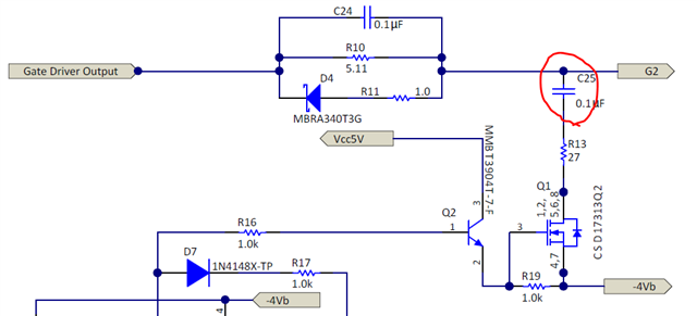
According to the design guide, when short circuit occurs, Q1 will turn-on and gate to source capacitance of the MOSFET will start discharging through capacitor C25 and R13. When I try to simulate, after detection of short circuit, voltage at G2 dips and then starts recovering back. Is this due to the presence of C25 in series with R13? Is C25 supposed to be placed in parallel with R13 (similar to C24 in parallel with R10). Can this circuit work properly without adding C25?
Further it has been mentioned that, after the gate voltage has reached 5.5 V, the second-level turnoff process starts. How is this voltage sensed by the comparator?
Thanks in advance.