This thread has been locked.

If you have a related question, please click the "Ask a related question" button in the top right corner. The newly created question will be automatically linked to this question.

PMP8740: PMP8740 Rev_E 2KW BC Boost plus Auxiliary Power supply

Part Number: PMP8740
Other Parts Discussed in Thread: LM5023

Hello

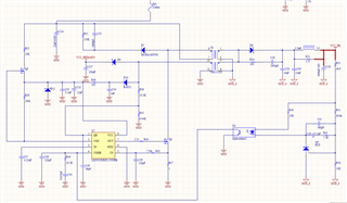
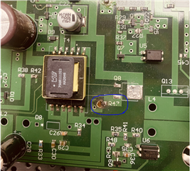
Iam designing PFC based battery charger. i am using the reference design of the auxiliary power supply given in the PMP8740 reference design(https://www.ti.com/tool/PMP8740#tech-docs) and  (https://www.ti.com/seclit/ml/slup348/slup348.pdf?ts=1669636312598&ref_url=https%253A%252F%252Fwww.ti.com%252Fproduct%252FUCC28180). schematic diagram of the circuit and the real hardware board are given below. when we supply rectified AC output to the RF1 fuse, the resistor R47(Rsense) got short circuited. we are unable to find the actual fault for this short circuit. for this purpose we inspect every component placement thoroughly and everything seems to be fine. can you please help us in this regard. 

Thanks

  • Hello Dania,

    This is a strange failure, I believe. Does also Q8 fail? If Q8 goes to short circuit, then, as consequence, R47 will be damaged.

    If, instead, Q8 survives and only R47 is damaged, the peak current rating of this resistor might be a problem. For example, in my design I have a 1206 package. From the picture you attached it looks to be 0603 or 0805. Can you please replace it with a peak-power (typically suited for current sensing) rated 1206 resistor?

    Furthermore, in my layout the distance between the source of Q8 and the controller LM5023 is ~ 11.2 mm. In your case I see tracks are routed out from Q8 towards the controller (which I cannot see): is the LM5023 far away? This shouldn't be the root cause of the failure, because the LM5023 is a cycle-by-cycle peak current limit controller, but you can experience unpredictable on-time generation and jitter, visible on the switch-node (drain of Q8).

    Thanks,

    Roberto