This thread has been locked.

If you have a related question, please click the "Ask a related question" button in the top right corner. The newly created question will be automatically linked to this question.

TIDA-01445: Why is a comparator used for LS current regulation/limitation in dynamic state

Part Number: TIDA-01445
Other Parts Discussed in Thread: LM2903, INA381-Q1, INA225-Q1, INA225, TPS2H000-Q1

Why is a comparator, in a Schmidt trigger configuration, used for the low side current limit in the tida-01445 design?


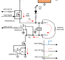
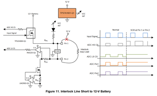
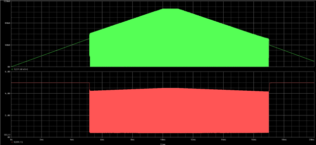
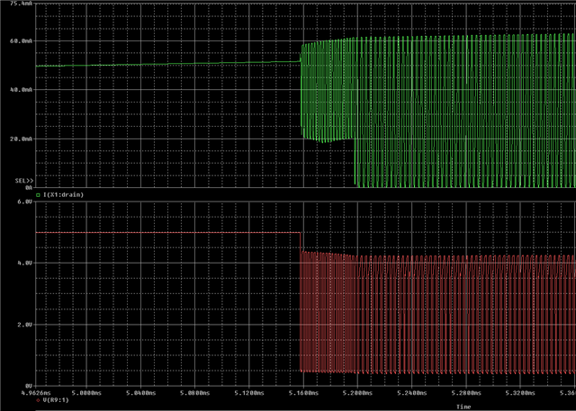
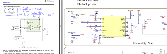
From my understanding the LM2903 comparator is used to limit the dynamic state current as well as the short to battery fault current to 50 mA (49.3 mA - 51.5 mA with hysteresis). Will the output of the comparator not switch back and forth rapidly between 0 and 5V? The FET is probaly not fast enough to completely switch on and off, in combination with C4, smoothing the interlock current.

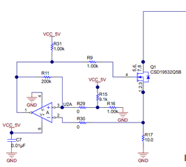
Still, I guess, the output of the LM2903 will resonate in the MHz range? Why was this the preferred solution, compared to an opamp, that regulates the current via the FET with an analog voltage level? I can imagine the resonating output to become an EMI issue. Therefore, I am interested why this design approach was chosen. Maybe there are some considerations, I don't see at the moment.

Thank for the clarification.

Best regards

  • Hello Michael, 

    I am not able to reach out to the author of this reference design but I will try to address your concerns. Let me please look into this first.

    Best regards, 

    Jiri Panacek

  • Hi Jiri,

    Thank you very much for your support.
    I'm looking forward to your professional expertise.

    Best regards

  • Well, I simulated the circuit and came to the same conclusion as you. 

    Simulation Circuit:

    /resized-image/__size/640x480/__key/communityserver-discussions-components-files/234/pastedimage1678440095618v1.png

    Output of the comparator vs the sensed current:

    /resized-image/__size/640x480/__key/communityserver-discussions-components-files/234/pastedimage1678440332434v4.png

    It is obvious that the output of the comparator quickly switches ON and OFF.

    /resized-image/__size/640x480/__key/communityserver-discussions-components-files/234/pastedimage1678440404280v5.png

    Simulation in pSpice for TI (without the DAT file that is ~50MB)

    /cfs-file/__key/communityserver-discussions-components-files/234/low_2D00_side_2D00_comparator_2D00_pspice.zip

    Here are my thoughts:

    • The circuit with the comparator is not "current limit" but "over-current detection".
    • The behavior is not latching - the protection turns off as soon as the over-current condition disappears which cause oscillations.
    • In my opinion, the author of this design expects that the microcontroller either monitors the output of the comparator (but the signal is missing) or detects the misbehavior on ADC_CS_HS and ADC_CS_LS signals.
    • The practical benefit of the comparator circuit is questionable.

    My suggestion:

    • I would remove the comparator circuit and use the INA381-Q1 instead of the INA225-Q1. The INA381-Q1 is a newer device that  is cheaper and integrates latching comparator. Would this work in your application? 

    Please note that even I deal with various automotive applications I am not an expert on interlock systems. 

    Kind regards, Jiri

  • Hi Jiri

    Thank you very much for your detailed answer as well as the simulation. Also the recommendation for a different current aplifier is greatly appreciated. Especially since the INA225 is out of stock everywhere.

    Regarding the current limit vs overcurrent detection I am still unsure:

    - The "over-current " situation is pretty much the same as the active state in my eyes.

    - During active state, when the HS switch is turned on, the loop current is only limited by the sense resistors, Ri of the HS switch, and IL loop (which can be close to zero), resulting in a low loop resistance below 20R. With a 12V sourve voltage, the resulting current would be way to high.
    According to the specs and the shown measurements in the reference design, the active state should be constant current at 50 mA. In my opinion the only way to achieve this constant current with the given design would be to use the low side FET as a variable resistor.

    - It can be seen in figure 11, that the current in case of a short to 12V supply is limited to the same 50 mA.
    The voltage measurements on pin 2 goes high, which means, pretty mcuh the whole supply voltage is seen as votlage drop on the LS current limit, indicating that the FET is limiting the current.

    - Chapter 3.2.1.2 shows that the active state IL current stays at ca. 50 mA, regardless of the 12V battery supply voltage, indicating a current control.

    - Therefore I believe, the low side constant current sink is needed for the application. Maybe the comparator was chosen because of preferred  functional safety behaviour.

    Thank you for your thought on this topic.

    Kind regards

  • Plase note that the HS switch device (TPS2H000-Q1) is configured as a current source with the maximum output current approx. 100mA. Please look at the pin CL in the datasheet (page18). The "normal" operation current is limited by the chain of external resistors (systems that are connected to the interlock such as inverter, DC/DC, etc.). This current has to be below 50mA which is the limit for the low-side, comparator-based, over-current protection. The author tested the interlock with an external resistor decade that set the interlock current between 5-55mA (Table 2).  

    I understand it the way that the PIN 2 terminal has to be protected against short to battery and short to ground. In case of the short to battery the current through Rcs and Rcl is limited only by the resistance. I believe that's the reason why the author added the over-current protection with the comparator.  

    /resized-image/__size/640x480/__key/communityserver-discussions-components-files/234/pastedimage1678787191166v1.png

    Kind regards, Jiri