This thread has been locked.

If you have a related question, please click the "Ask a related question" button in the top right corner. The newly created question will be automatically linked to this question.

PMP22075: I cannot get the full 12V output when the input voltage is less than 10.75V approx.

Part Number: PMP22075
Other Parts Discussed in Thread: LM5026

Hello, Texas team.

I have built up a PMP22075 using the gerbers etc supplied.

The design is described as having an input voltage range of 9V to 60V. 

My Problem - But when I reduce the input voltage, the output starts to drop from nominally 12V once the input voltage is less than approximately 10.75V.

Investigation so far - Duty CycleAs expected, I can see the duty cycle of OUT_A of the LM5026 increase as the input voltage reduces.

BUT the duty cycle hits a limit of about 73% - when the input voltage equals 10.75V approx.

  • With DCL connected directly to RT on the LM5026, we should be programming the maximum duty cycle.
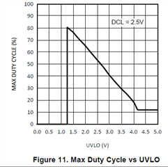
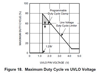
  • There is also a relationship with duty cycle and the UVLO voltage - Shown in Figure 11 and Figure 18 of the LM5026 data sheet.
    • The UVLO voltage is set by the resistor divider comprising R10, R13 and R17.
    • This appears to give 1.45V when Vin = 9V (9V x 10.5 / (10.5 + 53.6 + 1))
    • If UVLO is 1.45V then We'd expect max duty cycle to be less than 80% ?? - as shown in Figures 11 and 18.

  •          

My question:  Please advise how I can achieve a full 12V output when the input voltage is at the low end of the range (from 9V to 10.5V say)?

(Our application requires a minimum input voltage of 10.5V).

Thanks in advance.

  • Hi Fraser, have you tried testing the lower input voltage at lower output power? For example can you try this at half load or light load? It might be that the it's hitting it's current limit at lower input voltages. If this is the case, you can slightly reduce the sense resistor. Thanks!

  • Hi, Darwin.

    Thanks for your suggestion. but I experienced the same issue at lower o/p loads (0.6A, 1.2A and 2.4A).

    My Recent Findings - I found a similar reference design, PMP7892, that had a 20k resistor connected to the TIME pin of the LM5026. The PMP22075 design has a 143k resistor, R16, connected to the TIME pin.

    When I changed R16 from 143k to 20k, the PWM overlap duration reduced from 400ns to 60ns.

    I could now reduce the input voltage to approx. 9.7V without any reduction in the output voltage, 12V

    It seems that there is a relationship between the amount of PWM overlap time (of the main SW FET and the Clamp FET) and the maximum Duty Cycle that can be achieved?

  • Hi Fraser, for active clamp design at this frequency, I usually start with a overlap of 50ns-100ns. 400ns seems rather large and the datasheet only characterizes RSET up to 110k ohms. In general, you can set it to 2-3% the switching period. Looking at the test report it looks like ~6us period which would be ~120ns.

  • Thanks for your help, Darwin.