This thread has been locked.

If you have a related question, please click the "Ask a related question" button in the top right corner. The newly created question will be automatically linked to this question.

TIDA-00779: Current Limit Resistor Bypass Circuit Equation for 0.2s calculation and other Queries

Part Number: TIDA-00779
Other Parts Discussed in Thread: UCC28180EVM-573

Hi TI Expert,

Can you let us know how you calculated these 0.2s switch delays using which RC Values in the Design ?
Also, what is the importance of having 2 signal PFC ON and a rectifier(from 2 Diode) signal to turn on MOSFET by which Relay is triggered? Also, a Zener in Series will drop the voltage by 12V, but the MOSFET we select will turn ON at 1-2V only. Then how is the time calculated as 0.2s?

Please explain the given circuit with the equations and how it works.


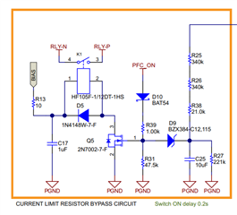
Also, if we do not want to use the boost follower circuit, then we have to use or consider the divider given in the image below for PFC Boost Circuit.


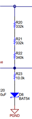
Waiting for your reply! 

Thanks & Regards,
Meet Devendra Pandya

  • Hi, Meet

    Based on the RC charging circuit R25/R26/R36/R27,  time constant is pretty
    smaller, however, since the rectified voltage on these resistors is
    pulse DC(because there is no E.CAP), so charging time will be much longer
    then normal RC charging time.

    As for boost follower circuit, you can ignore all of them including
    Q4, R14, C20, you can also refer to UCC28180EVM-573 for DC voltage sensing at https://www.ti.com.cn/tool/cn/UCC28180EVM-573

    Regards
    Hely