This thread has been locked.

If you have a related question, please click the "Ask a related question" button in the top right corner. The newly created question will be automatically linked to this question.

Power management forum

Part Number: CSD13306W
Other Parts Discussed in Thread: CSD25310Q2, CSD17483F4, CSD13380F3, TINA-TI

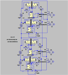
In the attached picture, CSD13306W is the NMOS model and CSD25310Q2 is the PMOS model. PMOS switches are in SSR configuration. The circuit is such that nmos switch is used to trigger PMOS switches in ssr configuration .In row of cell 3, transient spikes are coming in the voltage graph of VGS of NMOS ,though these transients are in uV. The graph is also attached .Additionally, no such transient can be seen if the resistance next to the PMOS is adjusted to raise the drain current through the PMOS to 5 A.  In other rows, where VGS is not 1.5, no transient can be observed. What is the reason behind these transients in Vgs graph of NMOS when Vgs is 1.5V?

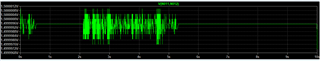
 Vgs Graph through NMOS of Cell3

  • Hello Anisha,

    Thanks for your interest in TI FETs. I'm not familiar with this type of application. Is this for cell balancing? From what I see in the diagram, VGS of the NFETs in cells 1 & 3 is driven to 1.5V when they're turned on. Similarly, VGS of the FETs in cell 2 & 4 is driven to 1.8V when they're turned on. Both of these levels are between the datasheet max VTH (1.3V) and the min VGS (2.5V) where on resistance specified. I think the oscillation may be because VGS = 1.5V is closer to max VTH and it could be causing some oscillation in the simulation. At VGS = 1.8V, the oscillation goes away because it is further away from VTH. In order to guarantee that the NFET is fully on VGS must be >= 2.5V. Otherwise, the FET is operating in the steep part of the Rds(on) vs. VGS curve as shown on page 1 of the datasheet. Small variations in the gate drive voltage, VGS, and/or threshold voltage, VTH (due to normal process variation) can cause large changes in Rds(on).

    Since you only have 1.8V to work with, I would recommend looking at a different NFET that has on resistance rated at VGS = 1.8V such as CSD13380F3, 12V NFET in FemtoFET F3 LGA package or CSD17483F4, 30V NFET in FemtoFET F4 package. Note, both devices have integrated single-ended gate ESD protection diodes. Take care not to drive VGS negative to prevent forward biasing the diode. If you can, adjust gate and gate-source resistor values to get min VGS = 1.8V.

    Lastly, what simulation tool are you using? If it's PSpice or TINA-TI can you please share it so I can take a look at it.

    Best Regards,

    John Wallace

    TI FET Applications

  • Thank you for your reply . Yes, you are right it is for cell balancing . I have attached the link of spice circuit . One more question I asked was that why no such transient can be seen if the resistance next to the PMOS, let say row of cell 3, is adjusted to 0.93 (3*1.8 -0.7 /5)ohm and resistance of other row is also adjusted accordingly to raise the drain current through the PMOS to 5 A , though vgs is still same across nmos . Also , using the n-mosfets as you suggested has no effect on the oscillation issue . 

    /cfs-file/__key/communityserver-discussions-components-files/234/Draft_5F00_afe.zip

  • Hi Anisha,

    Thanks for the update. At this time I don't have an answer to your question why there is no oscillation when the PMOS current is 5A while VGS of NMOS remains the same. I'm not sure how to open the simulation (.asc) file. What simulation tool are you using? I have PSpice and TINA-TI.

    Best Regards,

    John

  • It was LtSpice Tool. I have now attached the link for the simulation done on Tina -TI Tool . I hope you already got the idea  of the circuit .Also, in Tina-TI tool one error is coming ''Operating point not found'' . I have tried to find a solution of this error . But , I am not able to find it . Therefore , along with the oscillation issue it would be great if you also look into this problem .

    /cfs-file/__key/communityserver-discussions-components-files/234/AFE_5F00_sch.TSC

    Also ,one more point to add is we have to turn on both the consecutive rows to charge or discharge one cell. For Cell2 , we have to turn both cell 1 row and cell 2 row and vgs of both nmos are 1.8 and 3.6 whereas for cell3 ,it is 1.8 and 1.5 . In case of cell2 ,there is no oscillation but in case of cell3 ,there is oscillation in nmos whose vgs is 1.5 . 

  • Hi Anisha,

    I was able to download the TINA-TI simulation. There were a couple of warnings when it checked the wiring which I corrected. Can you tell me what type of analysis and the conditions you used to get the waveforms shared earlier. I'm not certain what I'm looking for.

    Thanks,

    John

  • Hi John,

    Thank you for correcting my circuit . I am not sure whether Tina-TI will give same results as LtSpice .But after correcting the connections , "Operating Point not found " error is still coming . When I tried with different NMOS model(2N6755) in place of T4,T8,T12,T16 and did DC analysis the nodal voltages are not coming right . These n-fets are not able to turn-on only. I don't know why this issue is coming now . I have attached the link as well.

    /cfs-file/__key/communityserver-discussions-components-files/234/1220.AFE_5F00_sch.TSC

    Also the conditions I have used to get the waveform are turning on both the rows of Cell 2 and Cell3 by keeping the DC voltage source at 12V and then oscillation or transients are coming in plot of Vgs (1.5V) of NMOS  (Cell 3 row).

  • Hi Anisha,

    I am using the simulation file as is. I can run a DC analysis to calculate the nodal voltages and a transient analysis. I'm not sure what I'm looking for. VS1 & VS2 = 20V and VS3 & VS4 = 0V. I'll do what I can to help you but not sure I can do much if I cannot replicate the oscillation. Is this causing a problem in your system?

    Thanks,

    John

  • Hi John,

    Yes, Oscillation is a problem and if it is happening I want to know the reason behind it and also there is one more issue in TINA TI that why NMOS model (2N6755) is not able to turn on .

  • Hi Anisha,

    I'm not able to get any useful results and have no answer to your question regarding the 2N6755 model. This is a very old FET and the model is included in the library. It wasn't created by TI. I'm sorry but I don't think I can help solve the problem with your simulation.

    Best Regards,

    John