This thread has been locked.

If you have a related question, please click the "Ask a related question" button in the top right corner. The newly created question will be automatically linked to this question.

PMP23340UCD: GUI Debug——Adjustment frequency

Part Number: PMP23340UCD
Other Parts Discussed in Thread: UCD3138A, UCD3138CC64EVM-030

Hi,guys.

      I'm having a problem and I need some advice.

      Hardware:PMP23340UCD(UCD3138A) 
      Firmware:TI supplied routines——UCDIBCFirmware 

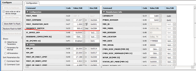
      Purpose: I want to set the output frequency of the DPWM of the source program in 500KHZ-1500KHZ through the GUI.

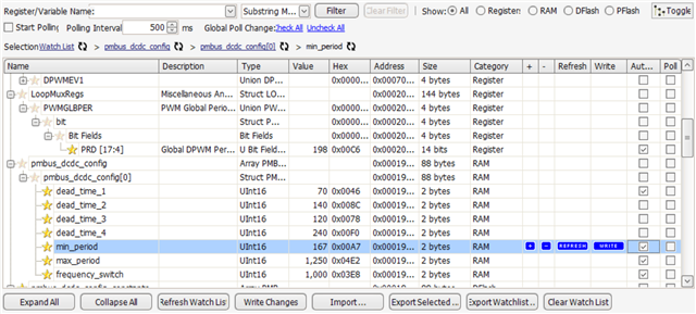
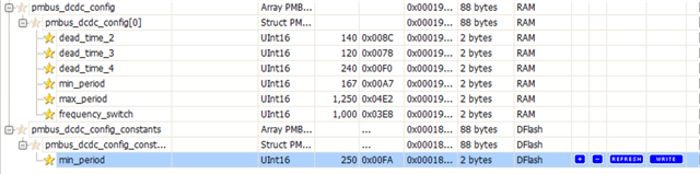
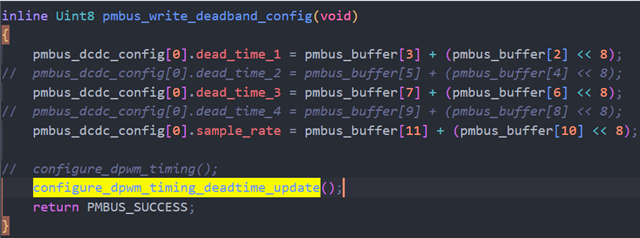
  1. At first I wanted to use the GUI to adjust pmbus_dcdc_config[0].min_period to change the output frequency.But the DPWM period register is not changed in any way. Probably because pmbus_dcdc_config[0].min_period is in RAM and no matter how I change it, it doesn't change the DPWM period register value.Am I doing or guessing right?
  2. In fact I had burned the source in UCD3138CC64EVM-030 and after that change of pmbus_dcdc_config[0].min_period the DPWM period register was also changed, but when I burned it to the PMP23340UCD it didn't work. I'm confused about this.
  3. I think if I change the initial value in flash, when the program reset, the value in flash will be copied to RAM and run in the program.So I tried to change pmbus_dcdc_config_constants[0].min_period, but it can't be modified in the GUI.
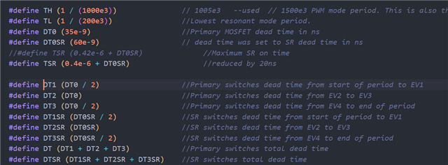
  4. Finally I tried to change the #define period which was initially in the source program and it does change the DPWM output frequency, but when I set the frequency below 900KHZ it doesn't work and doesn't detect the output waveform with VOUT. Even though at this point the DPWM period register is in sync with the value I set.
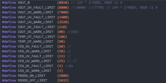
  5. Is it VOUT_OV_FAULT_LIMIT or some other setting that makes the board not work when the frequency is set below 900KHZ?What should I change to remove this restriction to meet my testing needs?
  6. It is troublesome to modify the frequency in the source programme and then burn it, where should I modify it in the GUI?

Best Regards.

  • Maybe my manipulations and guesses in the question above are wrong (I hope you can help with the confusion).This should help me understand the procedure.

    I found a way to change the frequency and as you said before in the 20% range, it looks right, right?

    So now how do I lift the 20% restriction?I would like to modify it in the range of 500KHZ to 1500KHZ for my testing needs.

    And I'm also curious how to change the frequency in the GUI Memory Debugger page.

    Best Regards.

  • Based on the information in the programme and the datasheet, I set the dead time as above - 18ns for DB0 and 36ns for DB1, but the returned reads don't match and DB1 remains unchanged at 35ns.

    How do I adjust the dead time correctly without being limited?

    In your previous answer you mentioned that the frequency and dead time can be modified within 20%, how can I lift this restriction?

    Then I found this in the code,Is it possible that the comment here is the reason why deadtime can't be written, and the comment here should be cancelled?

    What happens if I uncomment it? Why did you comment it out in the first place?

  • I can schedule a call with you to go through the firmware and GUI. What is your email address?

    Thanks,
    Sean

  • Thank you for your reply.
    Here's my email——Martin.Yang@etron.cn.

    What time is convenient for you?

    I look forward to speaking with you!

    Best Regards.

  • I am on vacation this week. I can talk to you next Monday. I am going to send you the meeting invitation. 

  • Hi Sean,

    Sorry to interrupt your vacation, but if you can see it, I hope to take a few minutes of your time .

    I'm trying to adjust the frequency through the GUI, but it's limited to 1000KHZ ± 20%.

    I tried to change it in the source program, but there are too many registers and numerical calculations to confuse me.

    Can you give me give me a clue? What parts should I analyze for modification?

    In fact, I tried to modify the code here and found that I could adjust the frequency outside of the limits,right?

    But I don't understand why this is so?

    May I ask what this part of the code does?

    Have a great vacation and I look forward to hearing from you!

    Regards,

    Yang.

  • Right, this is place you can change the band. For this board, it is not recommended to increase the frequency range. 

    The frequency output is controlled by filter output, here the code sets the clamp of filter output.