TIDA-010933: Some queries to use the reference design

Part Number: TIDA-010933
Other Parts Discussed in Thread: LMG2100R044, LM5164

Tool/software:

Hello,

We are going to design our own micro Inverter and we are refering the TIDA-010933 reference design for this purpose.

We have go through the reference schematic and there are some questions as mentioned below,


1) Should we follow the same schematic provided in TIDMCF8A.ZIP for our own design?
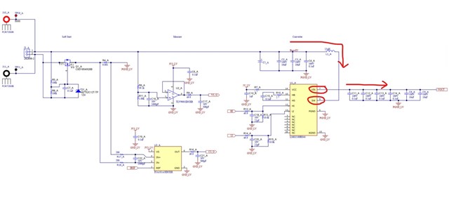
2) In our design, there is only the Input from the PV to the design, we are not going to charge the 48V battery OR power from 48V battery. As I have seen the U1_A, U1_B, U1_C, U1_D (LMG2100R044) pin#5 (sw) is connected to the PV voltage input and Pin#7(VIN) is connected to the vout. So this true for our application? Please find the below image for your reference.

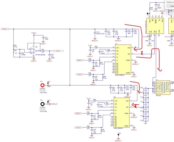
Where as the same IC LMG2100R044 is used in next stage which has the corrent connections look like, below is the reference Image,

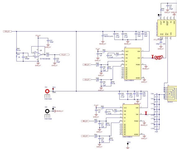
3) Do we need to add any Induction at the sw pin of either U7 or U9 for LLC resonant? Below is the reference Image. 

4) Initially, when we connect the EVM to PV at that time, MCU and other devices need the 5V and 3.3V so how it will be there on board, So kindly guide us the power topology at power ON and then after.


5)The MPPT stage needs to generate 75VDC as output. But the P&O algorithm will adjust the voltage to maintain the Point at Max Power, then how can it maintain the O/p voltage to 75VDC all the time?

Regards,

Alpesh

  • Hi Alpesh,

    1) Yes, you can follow the schematic for your design.

    2) If you are not going to use battery, than you don't need SoftStart schematic on the left side (with MOSFET) but the MPPT stage on LMG2100 will remain the same. The VIN pin is not only "Voltage In". I use this device as Boost converter when operating from PV panel, so the current going into SW pi and comun out from VIN pin.
    In CLLLC stage, two LMG2100 create a full bridge. In full bridge one leg is sourcing current and another is sinking the current.
     

    3) This is one of the features of the design - the lead inductor is build in the transformer. No need of external inductor.

    4) For testing purposes we have 5V jack connector on the board. But in real application there is LM5164 buck converter for self power supply. This converter is powered from 75V rail. At the startup a PV panel will charge 75V bus to some voltage through LMG2100 body diode. Then the board will be powered up and start operation.

    5) The MPPT stage operates as current source for the 75V rail, so MPPT stage is pushing current to the output to maintain MPPT. The 75 rail is not directly reguated. The 75V rail and the 400V DC Link are coupled with fixed frequency CLLLC. The DC/AC stage is regulating 400V DC Link voltage and as consequence indirectly regulates 75V bus too.

    Please let me know if something is still unclear.  

    Best regards, Seva.

  • Hello,

    Thank you very much for the details.

    Can you please provide me your email ID, so we can discuss the points through email as there are some confidential discussion need with you?

    Regards,

    Alpesh