


Tool/software:
Hello everyone, I start a topic about Tina-TI, about how I could model an LC antenna in Tina-TI.
I have a ferrite-rod core coil with its corresponding capacitance to resonate at a specific frequency. This kind of circuit is actually highly different in reality than in simulation. It presents a lot of losses and imperfection, which leads to quite consequent differences between simulation and reality.
I will go first with basic explanations about a parallel LC circuit, and some equations, then show a Tina-TI simulation and ask my questions about this topic.
Basic information about parallel LC resonators
Resonant frequency:
The resonant frequency f_0 for a parallel LC circuit is actually the moment where its impedance is at its maximum. It is given by:

Selectivity:
To be very selective, quality factor of this kind of circuit should be around 1500-2000, depending on the desired frequency and band-pass.
The quality factor is function of the carry frequency and the band-pass of our desired frequency range and is given by:
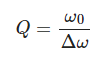
With:
- Q the quality factor
- \omega _{0} the center of our bandwidth (carry frequency)
- \Delta \omega the range of frequencies which we have interest to
Quality factor may also be calculated with the value of LC resonant circuit's component with te following equation:
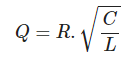
But on a perfect LC circuit, parallel resistance $R$ is considered infinite because it is an open-circuit and quality factor also infinitely selective.
>[!NOTE]
>However, in reality a quality factor is way much lower because of eddy current and other losses. We may reach a quality Q around 5-10 (maximum I could reach).
>[!QUESTION]
>Is there any way to reduce quality of the LC in Tina-TI, from a perfect component to something imperfect?
Simulate a signal received by the LC resonator
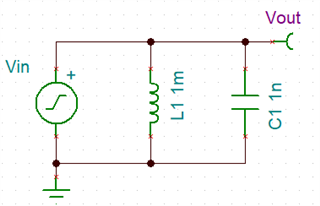
If I want to simulate the antenna, receiving an electromagnetic signal, I went with the idea to put an input signal from Tina-TI in parallel with the LC resonator. I went with the idea that my LC will be "polarized" by a signal, and only input frequencies will pass.
I made it currently with a signal generator from Tina-TI but I set it with an internal resistance value of 1T ohm I am not sure if it is correct to see it.
Test schematic on Tina-TI:
Frequency response bode-plot of circuit:
If I run the simulation, I have actually an extreme attenuation of my signal (approximately -100dB at resonant frequency) and the selectivity is quite high: the curve is sharp on diagram and phase shift is like perfect:
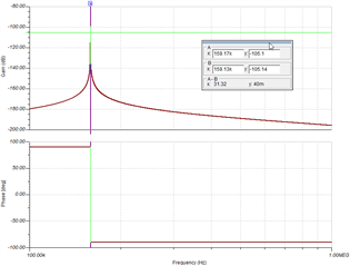
Here, the quality factor, were we consider out bandwidth being the frequencies were the amplitude of signal is equal to maximum amplitude -3dB then we have the following quality factor for this circuit:

The amplitude at this frequency on the bode plot is approximately -102 dB, which leaves us with a bandwidth of approximately 40 Hz. With our quality factor equation, we have Q:
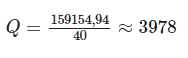
Which is quite high.
>[!NOTE]
>I guess that here, the quality is almost infinite and Tina-TI can't create the points very close around the carrying frequency. Those points should actually reach 0 dB, but the steepness is so high that the first points on bode plot only appears near -100 dB.
I am actually looking to model it because I want to analyze op-amp's different characteristics influence on the amplification circuit's quality. Especially:
- offset voltage
- input bias current
- input voltage and current noise density
The second reason is to look at which op-amp technology should be the most suited to be interfaced to this antenna and amplify its signal:
- Bipolar op-amp are used, but due to their significantly low input impedance, they tend to reduce quality gain, because the parallel resistance seen by LC circuit will be small. They have the advantage, however to have very low voltage noise density and very high GBW product (not always the case, we agree on that)
- JFET and CMOS based amplifiers do have today better and better voltage noise density, and they also present a very high input impedance, which is very useful to keep a high quality factor on our LC circuit.
>[!QUESTION]
>How should I model my LC antenna on Tina-TI to be closer to reality? Is there any elements I should give, like the model resistance of my capacity and inductance? Is it actually possible to model it? Does it make sense?
Best thanks in advance for your help and replies
Jeremie
