- Ask a related questionWhat is a related question?A related question is a question created from another question. When the related question is created, it will be automatically linked to the original question.
This thread has been locked.
If you have a related question, please click the "Ask a related question" button in the top right corner. The newly created question will be automatically linked to this question.
Tool/software:
Hello,
I'm using the UCC2895 for PSFB power converter.
I'm using it in voltage mode control.
In simulation the result are suitable but in practice, no stability with the feedback. In open loop, I haven't an issu.
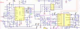
My question is, does the wiring correct for the voltage mode control ?

Many thank in advance, for your help !
Hello,
You had mentioned that you had this design simulated and it worked. You might want to compare your critical signals to your actual design to see what is different. This would be CS, The voltage amplifier output, the input voltage across your transformer.
If you are designing for voltage mode control you need a DC blocking capacitor in series with the transformer to prevent transformer saturation. If you don't have this it could cause and instability.
I reviewed your controller schematic. It looks like you are setup for current mode control. What you have looks like it is setup for current mode control with slope compensation added the the CS signal. However, your slope compensation is 700 mV which would be aggressive slope compensation considering the peak current sense signal should be less than 2 V. I would recommend reducing that the slope compensation to 200 mV. You can do this by decreasing the size of resistor R20.
I would recommend design peak current mode control over voltage mode control. When you do this you will not require a DC blocking capacitor in series with the transformer. You also have cycle by cycle current limit protection that protects the design from transformer saturation.
Also C30 does not seem correct. I would remove that capacitor and replace it with a short. If you want to have filtering for the CS signal a 100 to 220 pF capacitor from the ramp pin to ground will work with R19 to filter out high frequency noise.
Regards,