This thread has been locked.

If you have a related question, please click the "Ask a related question" button in the top right corner. The newly created question will be automatically linked to this question.

How to generate the GERBER files using WEBENCH DESIGN TOOL

Other Parts Discussed in Thread: LM25118, CSD18504KCS, CSD18504Q5A

Dear Sir/ Madam,

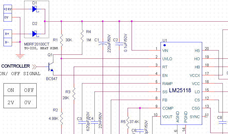
We selected Non isolated DC-DC BUCK-BOOST converter LM25118 for the required specification mentioned,

Input voltage range -  10.8 - 28 VDC

Output voltage         -   12 VDC

Output current          -   4A

We designed using WEBENCH DESIGN TOOL by changing some components and extract the schematic file and also board layout file of Altium but we doesnot find the gerber file in the board layout  document. We kindly request you to guide us the procedure to obtain the gerber file.

with thanks and regards,

Mohan Kumar K

Nandipowertronics Pvt Ltd.,

Bangalore - 5600079

Mob - 09986000128 

  • Webench does not generate gerber files directly. You can export your design to a number of schematic capture and PCB design software programs using the "CAD Export" tool. You can then use your PCB layout software to generate the gerber files.
  • Hi Mohan,

    John is correct that WEBENCH only provides the translation of the PCB files into various native CAD formats.  This offers for our customers an easy method to integrate and modify our proven power layouts into their larger system board design.  

    Since you have chosen to download the Altium file, it will require a fully licensed Altium PCB enabled cad tool to generate the gerber files.  If you don't have a fully PCB enabled version, I will be happy to help.  Please post the zipped file here.

  • Hi John & Howard,

    Thank you very much for your suggestions and i will do as per your guidelines by using CAD EXPORT of available PCB tool.

    And i attached zipped file of CAD EXPORT of Altium PCB file, since we not have the licensed Altium PCB tool hence i kindly request you to generate the gerber files.

    regards,

    Mohan Kumar K webench_board_exchange_design_4550214_2_Altium.zip

  • Hi Howard,

    I kindly request you to provide the Gerber file generated by using the attached CAD Export file of  Altium version of WEBENCH Design tool.

    with regards,

    Mohan Kumar K

  • Hi Howard,

    It's a pleasant reminder of requesting Gerber file.

    with regards,

    Mohan Kumar K
  • Hi Mohan,

    I sorry I did not see your first reply.   Please see the attached zip for the Gerbers.  Please feel free to contact me directly if you have other questions.

    howard.chen@ti.com

    4265.Gerbers.zip

  • Hi Howard,

    Thank you very much for your kind support and i will interact with you for more technical support.


    with regards,

    Mohan Kumar K

  • SRP1038A.pdfser2900.pdfHi Howard,

    We select the Power inductor of BOURNS (Make) & its part no: SRP1038A-150M, which is equivalent to TI WEBENCH TOOL recommend  part no: SER2915L-153KL of Coil craft (make). We kindly request you confirm the use of selected inductor is the right choice are need to select the alternative parts which has been recommended by TI WEBENCH tool.

    Please find the datasheets attached to the mail.

    With thanks & regards,

    Mohan Kumar K

  • While those two inductors are both 15uH, they are significantly different in size, current handling and DCR. You can easily see this by looking at the respective datasheets.
  • Hi John,                                                         Sorry for the late reply.. Ok thank you very much for your feedback.                                                                              With regards,

    On Monday, January 18, 2016, JohnTucker <bounce-24596@mail.e2e.ti.com> wrote:


    A Message from the TI E2E™ Community
    Texas Instruments


    JohnTucker replied to How to generate the GERBER files using WEBENCH DESIGN TOOL.

    While those two inductors are both 15uH, they are significantly different in size, current handling and DCR. You can easily see this by looking at the respective datasheets.


    You received this notification because you subscribed to the forum.  To unsubscribe from only this thread, go here.

    Flag this post as spam/abuse.

  • Hi John & Howard,

    Thank you very much for your kind support & now i tested the board it is working fine.

    Our design team recommends to select MOSFET of TO-220 package hence i select CSD18504KCS which is used for both BUCK & BOOST FET'S which is equivalent to WEBENCH recommendations (CSD18504Q5A & CSD16323Q3C) & i selected power inductor of Part no: 7447709150 of  Wurth Electronik make since in the last mail inductor found smaller core size & high resistance.

    And we designed this converter for driving system load of 12V/ 4A with nominal i/p voltage 24VDC obtained from AC-DC converter when utility supply is available, if utility supply is not available system load (12V/4A) will driven by the DCDC converter from sealed lead acid battery of 12V/ 18AH or 28AH. When it is working from battery we need to implement LOW Battery cutt_off, when battery voltage drops to 10.8VDC during discharge condition & to avoid deep discharge. Please suggest circuit to turn off power supply using UVLO or EN pin using microcontroller ON/OFF signal.

    Selected FET & power inductor is ok for the design.  Please find the Power inductor for your kind information.

    Thanks & regards,

    Mohan 7447709150.pdf

  • Now you are getting into design specifics about LM25118 rather than Webench or other generic questions. I have asked someone to take a look at it.  You might want to make a new post to non-isolated dc/dc forum.

  • Doc1.docxHello Mohan,

    The LM25118 has an EN pin that if dirven below 0.5V the LM25118 will be Disabled a voltage greater than 3V will turn on the LM25118.  Can drive the base of a BJT to turn on or off the LM25118.  Will need a pull up resistor. If you need a high out to enable and a low out to disable, you will need an addiotional transistor to drive the base of the enable transistor.  I hope this makes sense?  See attached.

  • Hi David,

    Thank you very much for your suggestions.

     Inline image 2

    Input to the DCDC converter is fed from schottky diodes, where input to D1 is 24VDC which is from AC-DC converter & FOR D2 it is 12VDC from battery. We used this scheme to avoid delay in change over from 24V to 12V, since D1 is at higher potential dcdc will work from 24vdc if it is turned off it will works from 12V.

    When dcdc is working from battery, we sense battery voltage using controller. When it drops to 10.8V, we will give low i/p signal to base of NPN transistor which turn off the base which results in 0V (less than 0.5V) at EN pin hence DCDC will be turned off & when battery voltage is higher than 10.8V transistor will be kept on by giving hign input signal from Microcontroller .

    Please verify & validate the scheme & also please give your feedback if any necessary changes in the ON/OFF circuit is required.


    Thanks & regards,
    Mohan

  • The emitter will always be ~VBE below the  base voltage.  If you supply 2V to the base, the emitter will be VBE below the 2V.  The EN pin high threshold can be as high as 3V for the LM25118.  Therefore I recommend using the schematic I sent.  This implementation will certainly turn the IC off but may not turn on?

  • Hi David,

    Ok we will use the ON/OFF scheme recommended by you. Thank you very much for your support..

    regards,

    Mohan

  • Power supply is working fine thank you very much for your support.

    We Kindly  request you to refer the tabulated inductor part suitable for our 48W (12VDC/4A) DC-DC converter with input range 10-28VDC. First two parts are recommended by Webench, but to make the module cost effective  we select the equivalent part as mentioned in the table. And also equivalent high current toroid inductors.

    Can we use the unshielded higher current toroid core inductor for our DCDC converter which can handle saturation problem.

     Please suggest us to select the cost effective inductor.

  • Hi David,

    Please give your suggestions on my previous Post related to Inductor selection.

    Thanks & regards,

    Mohan

  • Hi,

    You can certainly try.  Please note that unshielded inductors are prone to be more noisey and can possibley cause some noise issues.  I suggest you try a torroid that has an Isat rating higher than your peak currents at your vin min and maximum power out. 

    hope this helps?

  • Hi,

    Ok thanks alot for your suggestions.

    regards,

    Mohan

  • Hi David,

    We designed PCB Layout by referring layout recommendations explained in the LM25118 Datasheet & also EVM Module also.

    The Buck-Boost DCDC converter is working fine with i/p voltage 24VDC (Buck mode) and gives output voltage of 12VDC with full load of 4A.

    But with i/p voltage 12VDC (Battery 12VDC/ 14AH) the output voltage drops when load current increased than 2A & audible noise generate from the board, FB pin voltage drops less than 0.56V & COMP Pin voltage increases to 0.83V. 

    Please   guide us to solve this problem.

    Regards,

    Mohan

  • Hi Mohan,

    Can you share your schematic? It sounds like there is a stability issue when operating in Buck-Boost Mode.

    Are you seeing any oscillation on the output? If so what frequency?

    Thanks,

    Garrett