This thread has been locked.
If you have a related question, please click the "Ask a related question" button in the top right corner. The newly created question will be automatically linked to this question.
Hi,
Can you help to perform the AC analysis on TINA-TI.
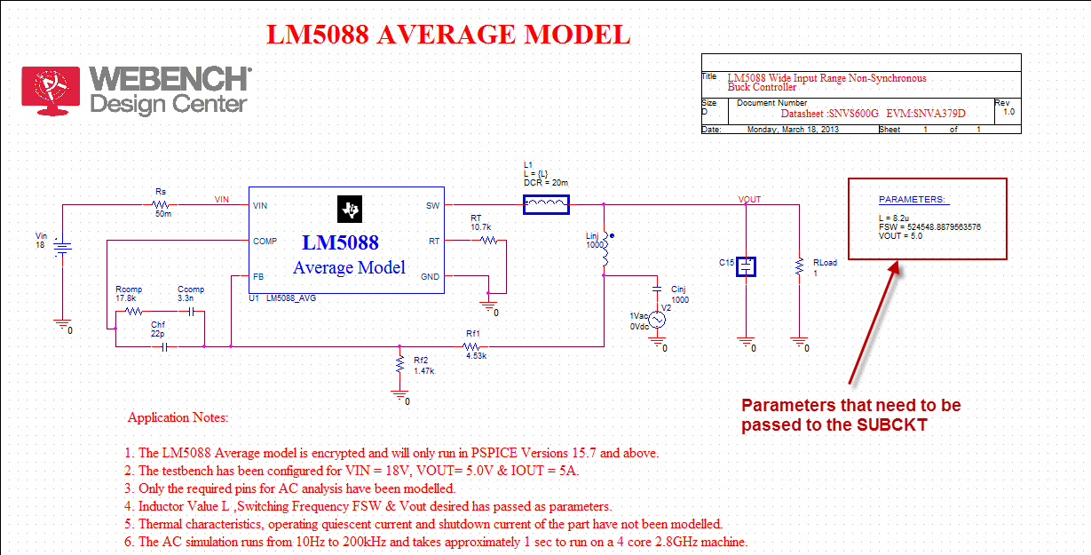
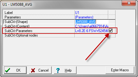
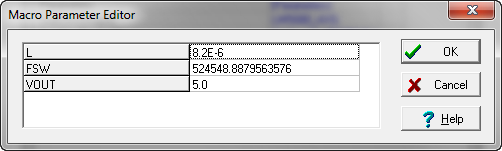
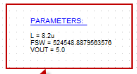
I was adviced to use LM5088 pspice avg model to run the AC analysis. Based on the app. note below, I'm trying to create new macro with LM5088 unencrypted models.
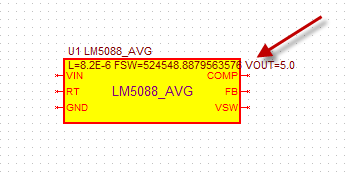
However, if I go to "New Macro Wizard" (Tool / New Macro Wizard), the wizard shows only 6pins, while the LM5088 is 16pin device. Also, the wizard does not allow me to uncheck "Show suggested shapes only." box, nor using "Search", selecting "Number of pins" and "Shape type".
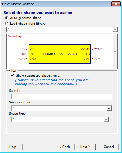
Can you help me to run the AC analysis with LM5088?
Thank you for your support in advance.
Regards,
Ken
Reference document
Importing a SPICE NetList into TINA9-TI
www.ti.com/.../slva527.pdf
My original post onto power forum.
[ LM5088 ] AC Analysis on TINA-TI
e2e.ti.com/.../2054572
Kenichiro-san,
The average models only model the loop and any parts of the IC that would affect the loop response. None of the average models will have the same number of pins as the actual device. The model is ONLY used for AC response (Bode Plot) of the loop and compensation (internal or external).
Your generation is completely correct and you should place the device into your schematic using the Insert-->Macro feature once the .TSM file is created and saved to your computer.
Here is what the circuit should look like once you create it (example for the PSpice reference design):
The PARAMS are being passed into the subcircuit in the TINA-TI model, but they are not displayed by default. In order to see them and edit them for your particular design, enter the macro properties (double left click) and you will see:
Make sure to check the box to display the parameters. Click on the line containing the parameters and then click on the ellipsis on the right side of the line:
Edit the values and save the edits by clicking on OK.
When you close the properties window, the schematic will update with the values:
You can now build your schematic around the model. You MUST use the Injection circuit with the large capacitor and inductor (Linj, Cinj, and V2 AC source from the picture). The output cap, inductor, load, FB resistors, and compensation network are then added. The inductor and Vout should match the values in the params statement for the model as these will be passed to the model, not the actual inductor value.
Please let us know if you have any further issues.
Hi Britt,
Thank you so much for detail explanation!
Let me try out!!
I will come back to you, if I have further question!
Thanks,
Ken
161220-LM5088 TINA-TI Transient Reference Design_16-12-20.TSC
Hi Britt,
I'm still working with my customer for this issue, then need your support now. Attached is our tsc file for AC analysis with LM5088.
Can you please take a look into this?
Also, we have a couple of questions.
<Q1: Total Inductance, Fsw and Output Voltage>:
Quote: "The output cap, inductor, load, FB resistors, and compensation network are then added. The inductor and Vout should match the values in the params statement for the model as these will be passed to the model, not the actual inductor value."
How can I see the total inductance of this circuit?
In your example, you have 8.2uH in params and L={L} in actual inductor. This means, no external value is needed. Correct?
Also, how is Fsw determined? Is that derived from PRAMETERS?
Wrt Vout, do you mean VOUT in params and resistor divided need to be matched?
<Q2: Injection Circuit>:
Quote: "You can now build your schematic around the model. You MUST use the Injection circuit with the large capacitor and inductor (Linj, Cinj, and V2 AC source from the picture)."
Do you have any of guideline, idea and/or tips to set the value of injection circuit?
<Q3: External Component>:
Your example does not have Cin, while there is a Cout.
Does this mean no Cin required for AC analysis?
Also, is it necessary to have Rs?
<Q4: Voltage Generator>:
It seems that your voltage generator and my one look slightly different.
Thank you for your support in advance.
Regards,
Ken
Kenichiro-san,
I have updated the .TSC file. It is attached below.
Here are the answers to your questions:
1.) The value being passed to the model is the L value of the inductor. You were passing 0 which is incorrect. It should be 6.8u since that is the value of your inductor. Please note that you have to specify BOTH values in the circuit. PSpice could use only one parameter. TINA-TI cannot. It must have both the inductor and the L value and both must be the same to get the proper simulation value. FSW is the switching frequency in Hz. I do not think that the circuit is operating at 250HZ, so I set it to 250KHz. Vout is the voltage output that is being set. This must also agree with the FB resistors that are chosen to get the proper simulation. In this case, I left it at 5V (I am assuming that is the Vout value for the circuit).
2.) You should not use the transient circuit to build the AC circuit. You did not add the injection circuit that makes the AC simulation possible. I have added it to the .TSC file below. It has an AC source, large inductor and large capacitor. This injection circuit "breaks the loop" from the frequency sweep for the Bode Plot.
3.) Cin is not usually important for the loop stability unless the input voltage is not stable. Since this is a simulation with a DC source, the source is stable and Cin is not going to effect the simulation. I have removed it from the simulation.
4.) You do not use an AC source for VIN for an AC simulation. I have changed this to a DC source for the AC simulation. For a transient simulation, I would use the source that you had originally.
I hope this information helps. I will double check the TINA-TI performance with the PSpice simulation. The magnitude looks correct, however, the phase waveform did not agree.
Kenichiro-san,
It appears that the current source was introducing a 180 degree phase shift in the TINA-TI simulation. When I changed it to a resistor of 0.714 ohms (7A at 5V), the simulation provided the same result as the PSpice reference design (I was using the resistor in PSpice).
Please see the attached .TSC file for the last iteration.