This thread has been locked.

If you have a related question, please click the "Ask a related question" button in the top right corner. The newly created question will be automatically linked to this question.

SN74CB3T16211: SN74CB3T16211 IBIS model can't configure as an output

Part Number: SN74CB3T16211

Posting for customer:

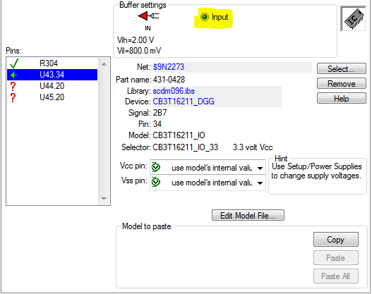
I'm using the IBIS model for the bus switch SN74CB3T16211 in the HyperLynx program to simulate the signal integrity of our PCB Layout and for some reason I cannot configure the model as an output. It only can be configured as an input which does not reflect the configuration we have on the board.

In the figure below, U43 is the bus switch and U44 and U45 are the Flash ICs which are configured as inputs. The signal under consideration is the address line from the MCU level shifted from 5V to 3.3V by the bus switch. 
 
Since there is now no driver in the simulation, I cannot get the required results. 

Am I doing something wrong?  How can this be fixed?

  • Hi Jason,

    It appears you are trying to set up the device as a switch.

    The following is a brief instruction on how to properly set up a switch model in Hyperlynx. Please give this a try and let us know how it goes:


    ***********************************************************************************************************************************

    1) You’ll need a driver and a receiver to connect the switch to.

    2) Place a MOSFET series, it’ll be on the left and looks like a CMOS.

    3) Select Models – Assign Models/Values by Reference Designator (.REF file)…

    4) In the Design’s parts list, select your component (e.g. U1), under Model/value, go to .IBS, and look around for your ibis file that has the switch model.

    5) Once selected, click on Assign Model, save your .REF file and close this window.

    6) You can then either double click on the box, or select and the go to Models – Assign Models/Values by Component.

    7) In this menu, choose a pin for connectivity. It should select the matching pin based on the model.

    8) Connect to your transmitter device and receiver and you can simulate.

    ****************************************************************************************************************************


    Eric Kim (WEBENCH Design Center)