This thread has been locked.

If you have a related question, please click the "Ask a related question" button in the top right corner. The newly created question will be automatically linked to this question.

WEBENCH® Tools/LM2735: Custom capacitor shows incorrect ESR and inconsistent simulation

Part Number: LM2735

Tool/software: WEBENCH® Design Tools

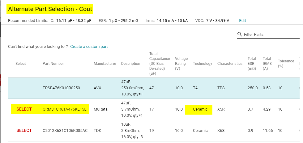
I'm seeing some odd behaviour in WEBENCH when I 'create a custom part' for Cout. This can be illustrated by comparison with Amod's shared design https://webench.ti.com/appinfo/webench/scripts/SDP.cgi?ID=2E2237E366C1AD75, which uses for Cout a 47μF ceramic, quantity 2 (derated to 39μF total with voltage bias) with ESR of 2.082mΩ each

I wanted to try some slightly different capacitors, so I started by creating a new shared design webench.ti.com/.../SDP.cgi using exactly the same components except for Cout I created a custom capacitor of 39µF with ESR of 1.041mΩ:

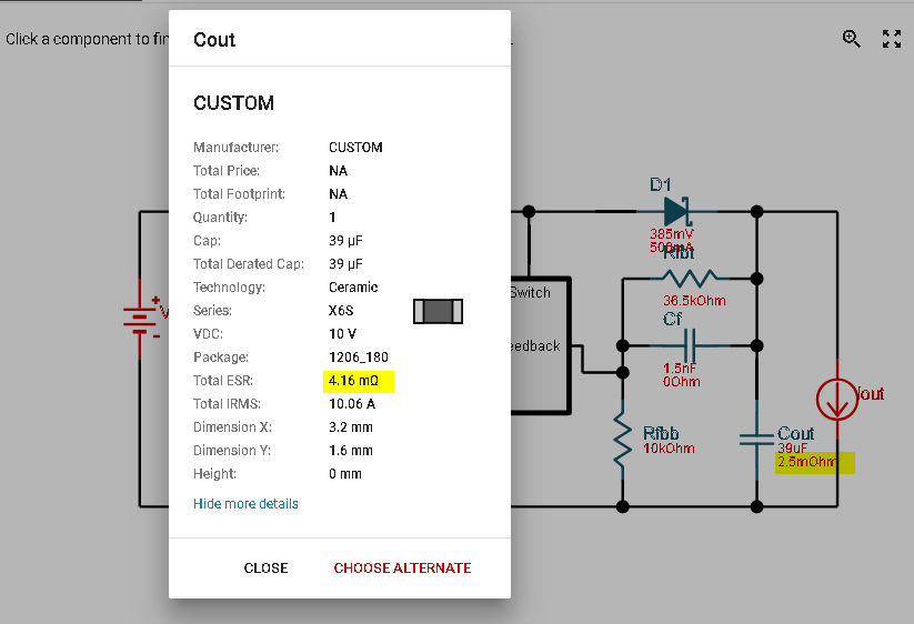
The first problem is that interrogating "More details" for this part shows an ESR of 250mΩ, unchanged from the default capacitor WEBENCH currently suggests for this design:

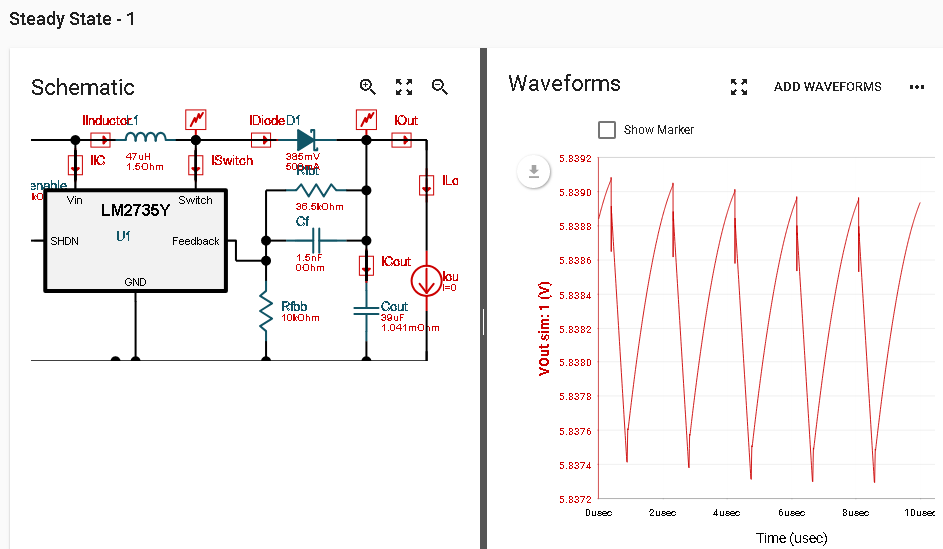
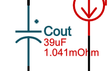
The next issue is with the simulation. The capacitor looks correct in the schematic shown on the simulation page:

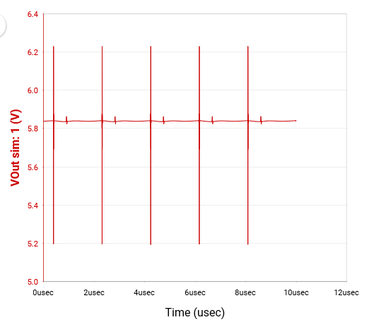
However, the steady-state simulation result shows huge spikes on Vout:

The Vout waveform does not appear to be consistent with the current through Cout:

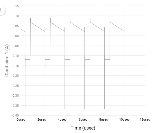
If the ESR was 1.041mΩ as intended, the spikes on Vout should be about 0.4mV peak-to-peak when the regulator switch turns on and about 0.2mV p-p when the switch turns off, or if the ESR is wrongly using the 250mΩ value the spikes should be about 100mV p-p and about 50mV p-p respectively, whereas in fact they are about 1.1V p-p and 40mV p-p respectively. Also, the other features of the current waveform (roughly rectangular, with droop in the high state) do not show up on Vout, either scaled by ESR or integrated by the capacitance (examples of each are in my previous post "Suggested output capacitor gives excessive output ripple" (https://e2e.ti.com/support/tools/sim-hw-system-design/f/234/t/784345).

Note that the above issues are different from the bug with parallel capacitors ("Qty" greater than 1) already reported as point 2(d) in the thread "Inconsistent options for alternate parts" (https://e2e.ti.com/support/tools/sim-hw-system-design/f/234/t/779121). In that case "More details" displays the wrong ESR (multiplied by Qty rather than divided) but the simulation appears to be correct. In the above case the ESR is displayed as that of the default component and the simulation looks completely wrong, unless I'm missing something.

  • Hi Richard,

    Apologies for the inconvenience caused.

    We are able to reproduce issue w.r.t ESR not getting updated when we choose CUSTOM capacitor.

    I tried updating ESR to 2.5mohm. It is showing up as expected in the schematic but has a bug when we click on component to see the properties.

    But it uses proper value (here 2.5mohm) when we run the electrical simulation. We will work on fixing the ESR issue.

    Also we are working on fixing issue w.r.t Vout(ripple) calculation displayed in Operating Values table.

    Thanks for your patience.

    Best Regards,

    Harish

  • Hi Harish,

    Thanks for your reply, and I'm glad you're addressing the two issues of ESR not being updated for custom capacitors, and the Vout ripple calculation. You didn't mention the other issue of strange simulation results - does that mean you cannot reproduce the waveforms I submitted?

    I did have a further thought about this - the anomalous steady-state waveform for Vout is possibly consistent with the custom capacitor having some series inductance. I've been running simulations of these circuits in PSpice for comparison (using the unencrypted LM2735Y model from your website), and they agree pretty well with the online WEBENCH simulations when I use standard capacitors. When I use a custom capacitor PSpice still gives believable results but the WEBENCH simulation is very odd, as reported in my post above. However, if I add about 0.7nH of inductance in series with Count in my PSpice simulation it looks remarkably similar to the result from WEBENCH simulation. Could it be that the custom capacitor is modelled with some inductance, whereas the standard capacitors are not?

    Richard

  • Hi Richard,

    I tried changing Cout to Custom capacitor with C = 39uF(derated value) and ESR = 1.041mohm for the design shared by Amod (https://webench.ti.com/appinfo/webench/scripts/SDP.cgi?ID=2E2237E366C1AD75). The results seem fine to me. 

    Below is the snapshot FYR.

    Kindly let us know if you are observing different behavior. It would be great if you can share your design again by following below procedure.

    Thanks & Regards,

    Harish

  • Harish,

    As requested, I have shared my same design again as webench.ti.com/.../SDP.cgi. Before sharing it I ran the steady state simulation again (without changing the circuit) and got the same results as before:

    I then did what you did, opening the design shared by Amod (https://webench.ti.com/appinfo/webench/scripts/SDP.cgi?ID=2E2237E366C1AD75) and modifying it with the same custom capacitor, and this time I got the same simulation result as you did:

    The mystery is: what's the difference between these two apparently identical designs, and how did it happen? The only visible difference I can see between the two schematics is that on mine, the inductor L1 has its series resistance 1.5Ohm labelled twice. This often seems to happen when I 'choose alternate' inductor, which I had to do because the default being suggested by WEBENCH is now 68µH, so it didn't match Amod's design which was created earlier when the default was 47µH. As I mentioned in point 2(c) of the "Inconsistent options for alternate parts" thread (https://e2e.ti.com/support/tools/sim-hw-system-design/f/234/t/779121), this seems to have changed within the last couple of weeks.

    Regards,

    Richard

  • Hi Richard,

    We are unable to reproduce the issue w.r.t Vout profile. We are observing triangular waveform from your shared design.
    However we shall keep a close track of this behavior in the WEBENCH. Thanks for reporting this.
    Yes, the DCR (inductor DC series resistance) shows up twice in the schematic. But it is considering only the single DCR value while perform electrical simulation. So, this shouldn' t be the reason for difference in the Vout profile.
    Regarding your query on "Inconsistent options for alternate parts": We keep updating our database by including new inductors, capacitors etc and there is possibility of getting different solution as the "Alternate Parts" showing up is within the Recommended Limits.

    Thanks & Regards,
    Harish
  • Hi Richard,
    We are working on fixing Vout ripple equation for LM2735Y and capacitor ESR display issue. The changes will be available on ti.com by next week. We will update you once the changes are on ti.com. Thanks for your patience.

    Best Regards,
    Bhushan
  • Hi Richard,

    Inconsistency in your simulation after changing capacitor to custom is due to below reason.

    By default for your input condition (Vin 4.38-5.25, Vout = 5.83, Iout = 0.12) tantalum capacitors get selected. Usually tantalum caps will have higher ESL(Equivalent series inductance ) compared to ceramic counterparts. High ESL could lead to spikes in Vout. 

    So when you change capacitor to custom, it takes Tantalum cap model for electrical simulation. 


    If you are looking to simulate using ceramic custom cap follow below steps.

    1. First select any of the ceramic cap from the alternate part list.

    2. Then create the custom cap and perform electrical simulations. 

    Kindly let us know in case of any queries.

    Thanks & Regards,

    Bhushan

  • Bhushan,

    Thanks for confirming that this is due to modelled ESL (series inductance), as I suggested in my second post on 20 March above. The fact that it depends on the history of the capacitor (whether it was tantalum or ceramic before customisation) is extremely non-obvious, and I'm sure it will trip up other users of these tools. I think it would help a lot if WEBENCH could display ESL explicitly in the 'More details' box that you see when you click on a component and also as an additional entry in the 'Create custom' dialogue for capacitors, so that you can set it to zero as part of the customisation rather than having to go via a standard ceramic capacitor first. It would also be a good idea to show ESL as an extra column in the 'Alternate Part Selection' dialogue.

    I'm pretty sure this explains all of the inconsistent behaviour noted in previous posts above, including that between Amod's and my apparently identical designs (I assume his custom capacitor started as a ceramic, while mine started as a tantalum). I was able to 'fix' my version my changing the custom part to a standard ceramic then back to a custom one, and I did then get a small triangular ripple on Vout instead of the large spikes. I note that the ESR display issue for custom capacitors has also been fixed - thanks for that.

    Incidentally, I had a bit of trouble getting a new simulation to run with my changes to Cout, because those changes repeatedly failed to 'stick' on the Simulate page and sometimes were even undone on the Customize page. I mentioned similar issues in another thread (point 2c in my third post in https://e2e.ti.com/support/tools/sim-hw-system-design/f/234/t/779121 ) and someone else raised similar concerns in https://e2e.ti.com/support/tools/sim-hw-system-design/f/234/t/787117 - Amod's reply to that one said that the schematic for simulation should update if you go back to Customize and then again select Simulate, but I found that even this didn't do it reliably. Ctrl+F5 (which I think reloads from the server rather than using the browser cache) still didn't fix it for simulation, although it did (at least sometimes) for the Customize page. In the end I had to delete my entire browser cache before the modified values would 'stick' for simulation.

    Some of this may be aggravated by the fact that our corporate network is currently suffering an intermittent slow internet connection, but if there's anything your software developers can do to make the tools more tolerant of a poor internet connection, that would be helpful. Let me know if you want me to raise this as a new thread.

    Regards,

    RIchard

  • Hi Richard,
    We are not able to reproduce the issue regarding, the changes not sticking to schematic in Simulate view. Kindly create the new thread if you face this issue again or for any other issues/feedback.

    Thanks for all the suggestions. The feedback has been forwarded to the concerned team. We are working on double DCR display issue. We will update you once the fix is available on ti.com

    Thank & Regards,
    Bhushan
  • Hi Richard,
    The double DCR display has been fixed and will be available on ti.com by next week.

    Regards,
    Bhushan
  • Hi Richard,
    The double DCR display has been fixed and change is now available on ti.com.

    Regards,
    Bhushan
  • Thanks Bhushan, I can confirm that the double DCR display is fixed for a new design and when opening a copy of an existing design (from a shared link). Opening an existing design from the My Designs list still shows the double DCR display, but that's not a serious problem.

    I haven't yet marked this thread as Resolved, since I'm hoping to see my suggestion about displaying capacitor ESL addressed (see my April 2 post above).

    Regards,

    Richard

  • Hi Richard,
    Thanks for your valuable suggestions. We have forwarded the same to concerned team. We are looking into the possibility of implementing a solution on Webench. This may not be taken up immediately.

    Regards,
    Bhushan