This thread has been locked.

If you have a related question, please click the "Ask a related question" button in the top right corner. The newly created question will be automatically linked to this question.

TIDA-010015: Power supply - With Full load not turned ON (Hiccup mode)

Part Number: TIDA-010015

HI All,

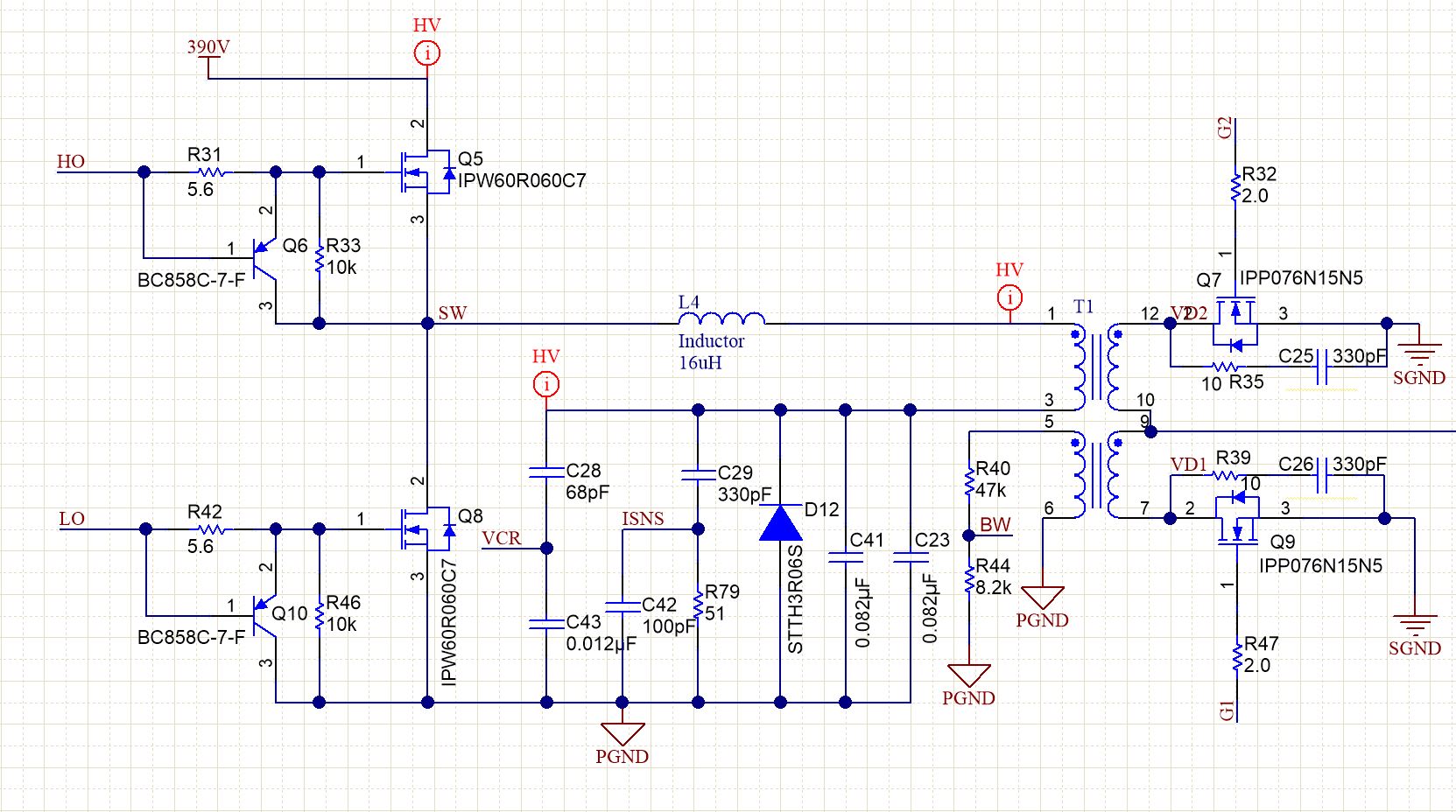
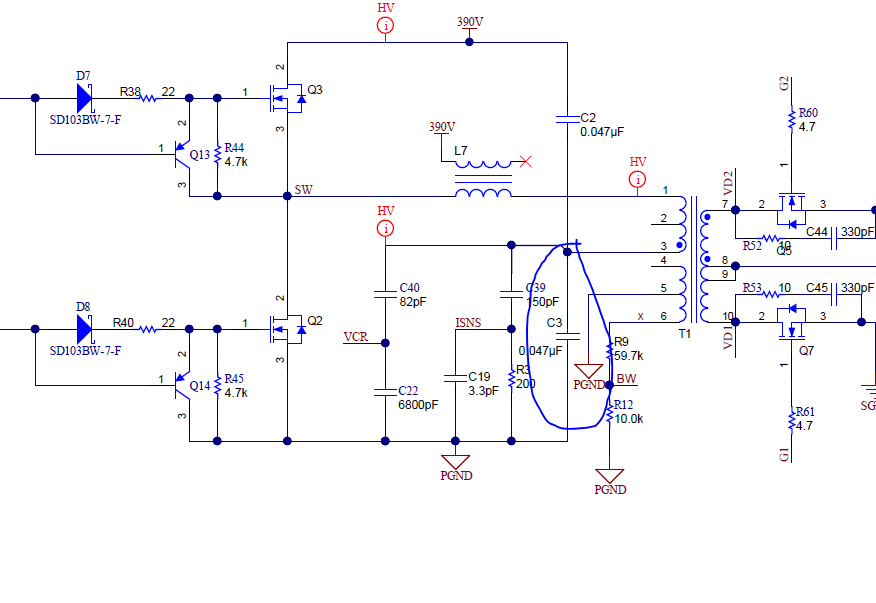
We have designed TIDA-010015 based power supply . Here some improvement required like with full load power supply not able start with that(going into hiccup mode), only it will start with nearly half load or less than half load.

What could be done here to start the power supply with its full load? 

What parameters need to change here to make it possible here ?

Expecting experts comments here to solve this issue. 

BR,

Bala

  • Hi Bala,

    From my understanding, it is triggered by Over Current Protection during startup time.

    Proposal my side:

    1. Decrease the resistor of RISNS gradually, check the startup characteristic;

    2. If it is possible to decrease the output capacitance or not;

    3. If you have current probe, please check if there is overshoot output current during startup. If yes, it will falsely trigger the Over Current Protection;

    4. You can try  to check the board could power on normally with CR mode load;

    Thanks!

    BR

    Cheng

  • Hi Cheng,

    Thanks for the response. Please clarify the suggestion from your side for my understanding. 

    1. Decrease the resistor of RISNS gradually, check the startup characteristic;

    ---If i decrease the RISNS, it will affect over current protection setting, then how the OCP will be triggered here?

    2. If it is possible to decrease the output capacitance or not;

    ---Hope your are meaning Transient due to capacitance (we are using same as ref design values)

    Rest I will check and let you know if i need more support from you. 

    BR,

    Bala

  • Hi Bala,

    1. Decrease the resistor of RISNS gradually, check the startup characteristic;

    ---If i decrease the RISNS, it will affect over current protection setting, then how the OCP will be triggered here?

    Cheng: Yes, it will affect the OCP setting. For the resistor RISNS now you use, what is the over current protection point? I think it is needed to increase the OCP setting. For TIDA-010015, the designer is transferred to other team, and this design is just assigned to me. 

    2. If it is possible to decrease the output capacitance or not;

    ---Hope your are meaning Transient due to capacitance (we are using same as ref design values)

    Cheng: It means the output electrolytic capacitor. You can decrease the output electrolytic capacitor count.

    Rest I will check and let you know if i need more support from you. 

    BR,

    Bala

  • Hi Cheng,

    Please find the response. 

    1.Currently the OCP is 25A as per reference design.

    2.For this count reducing in Electrolytic cap i will do one round of test and let me observe the result.

    BR,

    Bala

  • Hi Bala,

    1. I think you could increase the OCP point to about 27A or 28A;

    Also there is a method that you could place a SMD 600V ultrafast diode to be paralleled with the resonant capacitor, for example: MURS360T3G.

    It will also be helpful for the OCP triggering during startup.

    BR

    Cheng

  • Hi Cheng,

    Thanks for the input. Will try to increase OCP limit . Our design will support till 600W (25A nominal ) it suppose to be 30A OCP but now we are testing with 27A.

    Any way will try to increase OCP and try one round of testing. 

  • Hi Bala,

    Normally, the OCP point is about 130% of the full power rating. 

    You could increase the OCP point.

    Besides, I mention that you could put an ultra-fast diode (MURS360T3G) to be paralleled with the resonant capacitor. We have tried this method in our side and find this method is helpful.

    BR

    Cheng

  • Hi Cheng,

    Yes we will consider this diode parallel with resonant cap and OCP with 130%. Meanwhile we have one more issue with this TIDA-010015 model. With low input AC voltage this Active inrush section (MOSFET and Fusible resistor) getting too hot and some time this resistor smoking this happens only at below 90VAC. We have no idea how this FET and resistor parameters calculated here. 

    We figured some other design have NTC thermistor in place of fuse resistor.Shall we try this same here ? will it work ? How to select the NTC thermistor in that case.

    Please help here. It would be very helpful that we have oly feew more bug to close this design for further validation process.  

    BR,

    Bala

  • Hi Bala,

    For the active inrush section,  the operation principle is as below:

    1. During the startup time, the charge current of ECAP is flowing through the fusible resistor to take the anti-inrush current; 

    2. After the PFC goes into the steady-state, the MOSFET will work to short the fusible resistor.

    I think it could use NTC thermistor to replace the fusible resistor. I am not sure how to select the NTC thermistor, you could refer to the other design.

    BR

    Cheng

  • Hi Cheng,

    Can you point out on which location we need to use this Diode (MURS360T3G) . Please help here. 

  • Hi Bala,

    Please refer to the connection of the diode as below figure.

    Have you checked those method I told you yesterday?

  • Hi Cheng,

    Yes Tried this increase in OCP threshold  not working for us. Let me try this diode method and confirm you. 

  • Hi Cheng,

    Is it ok to place at this marked location? (C3)?

    We have connected LED based load while controlling dimming action seems like due to inrush, our power supply completely turned OFF at the secondary. 

    Whether is it because of power supply not capable of driving with load? or any other problem it could be?

  • Hi Bala,

    Please refer to the figure below: