This thread has been locked.

If you have a related question, please click the "Ask a related question" button in the top right corner. The newly created question will be automatically linked to this question.

WEBENCH® Tools/LM2735: Boost output voltage drops increasing load

Part Number: LM2735

Tool/software: WEBENCH® Design Tools

Hello,

i created a design in WeBench for the LM2735X with Vin in the range 3.7-4.2V and Vout = 5V @ 1.25A, and it gave me this schematic:
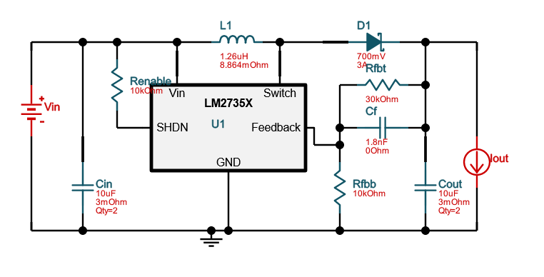

Even though in the datasheet a curve is not given for the 5V output, i then went on to build and test the circuit: i hooked it up to my generator to keep track of the current absorbed, while monitoring the output with a multimeter: the output voltage of the circuit is more or less constant up to 200mA draw, afterwards it starts dropping, all the way down to 3.8V if i try to sink 1A; i ran these tests loading the output with power resistors.

By looking at the waveform in WeBench, i see the inductor current has spikes up to 2.1A, about what the LM2735 is rated for: am i asking too much to this device?

The coil i used is Bourns SRN5020TA-1R2Y, which should have a high enough Isat of 4A, but reports 20mOhm DCR, almost double of what WeBench suggested, could this be the limitation in my circuit?

Perhaps my problem cannot be solved with this device: i'm trying to boost from a li-ion battery (hence the 3.7-4.2 Vin) up to at least 5V@1A, but since i don't own a hot air soldering station i'm trying to use components in footprints that, albeit small, can still be soldered with an iron and a very small tip; so, i'm open to any suggestion, should i have to turn my attention to a different purt number.

  • Hi Luca,

    The inductor you chosen is good for this application. LM2735X has a 2.1A minimum switch current limit. It should be able to output 5V up to 1A from 3.7V input voltage.

    Can you share the layout? The layout has big influence on the performance.

  • Hi Zack,

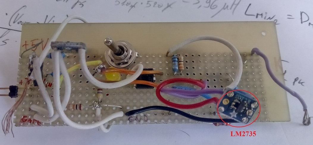
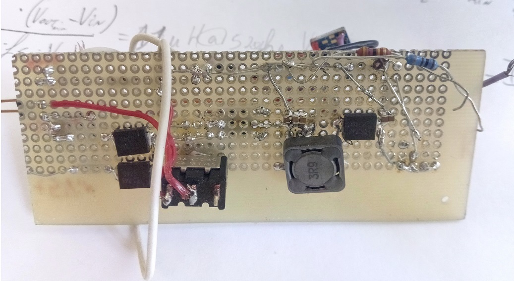
    i was leaning on the layout to be the issue, this being a relatively high frequency application; i had already repurposed the board to test out the LM2735Y, which yielded better result, if not completley satisfactory.
    I believe stepping down from 1.6MHz to 520kHz is a huge help in a hand wired, messy board...


    I have availabe a small 2-channel PICOscope which should still work at 1.6MHz, which waveform should i monitor to confirm that the layout is indeed the root of the problem?

    Thanks,
    Luca Ferioli

  • Hi Luca,

    For high frequency switching power supply, we don't recommend testing it with a hand soldered board. The big parasitic inductance of wire will cause high voltage spike on SW pins, which may destroying the device. Current flowing through the parasitic resistance has big voltage drop, may affect the feedback accuracy, causing output voltage dropping at high load current.

    Please see the details in datasheet layout guidelines part. It will tell you how to do the layout.

    I suggest you make a PCB to do the test. You can also buy / apply for a EVM on ti.com.