Other Parts Discussed in Thread: INA326, , INA333, ADS8866
Tool/software: WEBENCH® Design Tools
Hi everyone,
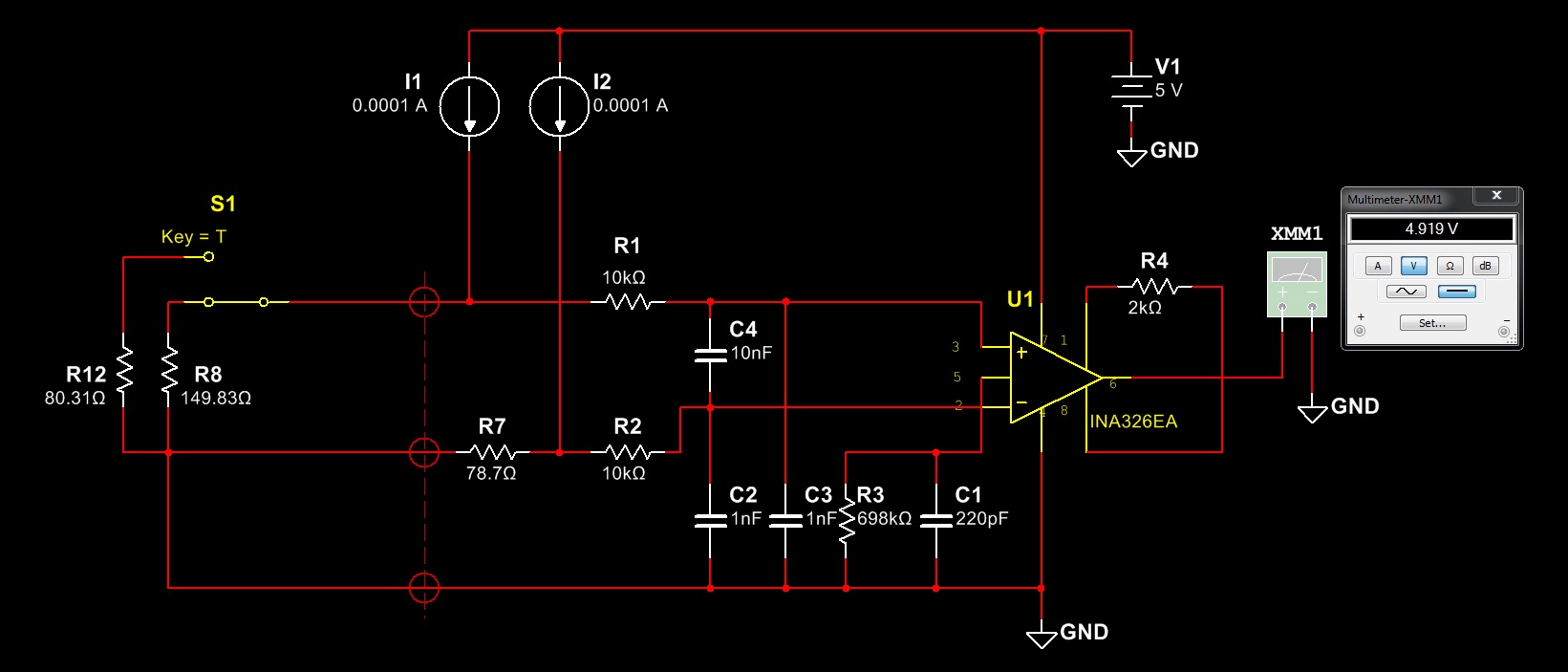
with reference to the TIDU969-May 2015, I performed a simulation with Multisim 13 from National Instruments, reporting exactly the same scheme, but the simulation results are absolutely different from what was expected and reported on the application note.
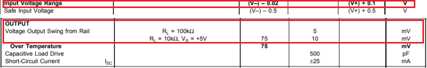
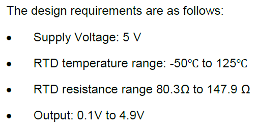
The output voltage value with RTD value 80.31ohm at -50 ° C is 0.117V as reported in the application note, but the RTD value at 150 ° C reported in table 3, of 149.94 ohm, is incorrect and should be 157.33 ohm. However, apart from this error, setting the wrong value of 149.94 ohm (which does not exist in the table of ITS-90 and alpha = 0.00385 values), the output voltage is not 4.82V, but close to the saturation of the amplifier , or 4.931V. By setting the RTD value 149.83ohm, i.e. at 130 ° C, similar to that of the TIDU969 application note, the output voltage is still not close to 4.82V, but 4.919.
Where is the problem?
Could it be that the Multisim Spice model for the INA326 component is wrong?