This thread has been locked.

If you have a related question, please click the "Ask a related question" button in the top right corner. The newly created question will be automatically linked to this question.

TIDA-00488: Question for MPPT configuration

Part Number: TIDA-00488
Other Parts Discussed in Thread: BQ25505

Hello expert,

I have question for TIDA-00488's circuit regarding BQ25505.
In the schematics, this design use 4.12M ohm for Roc2(High side) and 5.78Mohm for Roc1(Low side).
Then, this configuration will achieve 58% MPPT. But schematics said it will be 79.4%.
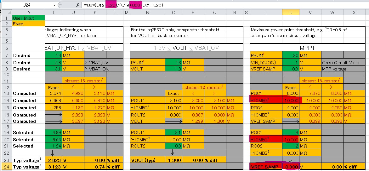
Moreover, user's guide calculate MPPT by following formula.
・(Roc2+10M)/(Roc2+Roc1+10M)
However, I cannot found this additional 10M ohm register between not only R1 and VIN_bq but also R2 and GND.

Then would you answer following question?
・Where is this additional 10M register?
・Does this circuit truly achieve 79.4% MPPT?
・Would you explain why this circuit achieve 79.4% MPPT if above question's answer is yes?

I'm looking forward to hearing back from you.


Best regards,
Kazuki Kuramochi

  • Hi Kuramochi-san,

    The engineer who made this reference design is no longer in the group.  I agree that those resistors will not give 79.4% MPP.  The datasheet formula and the spreadsheet at the link below provide the correct resistor values.

    Regards,

    Jeff

  • Hi Jeff-san,

    Thank you for your swift reply.

    I have question for your provided file.
    You explained TI deigned calculation is probably wrong.

    However, your provided file is using additional 10Mohm on ROC1 as follows.
      
    Then, I suspect that this 10Mohm is used for simplified estimating actual resister value.
    This is because, it is easy to found the 2 resisters combination which is almost 10Mohm. Therefore register divider for defining MPP should be 2 adjustable register and 10Mohm fixed register if expected RSUM is 20Mohm.

    So I guess formula of calculating MPP is as follows.
    MPP = ROC1(8Mohm+10Mohm) / ROC2(2Mohm)+ROC1(8Mohm+10Mohm)

    Also, when I go back to first question, I guess TIDA-00488's schematic forget to add 10Mohm series resister between R2 and GND.

    Would you tell me your opinion for my assumption?


    Best regards,
    Kazuki Kuramochi

  • HI Kuramochi-san,

    Your assumption is correct.  To reduce the current pulled from the input source, we recommend a sum total of 20Meg ohm.  You don't have to use that large of resistance.   But if you do, to make it easier, given the limited resistance values in the multi megaohm range, we recommend added a series 10Megohm resistor.

    Regards,

    Jeff