Other Parts Discussed in Thread: CC2640, SYSBIOS
Hello. I'm having issues with reading any data from a Sensirion SCD30 I2C sensor. Using the i2ctmp example and the examples from the I2C.h File Reference, I had successfully connected an SHT30 sensor and CCS811 sensor. However, I'm having difficulty doing the same thing with the SCD30 sensor.
For example, to read the firmware version, I first send the "read firmware" command 0xD100 in the 1st I2C transaction, then read 2 bytes in the 2nd transaction (since SCD30 does not support repeated start condition).
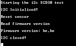
However, I get incorrect data every time:
I've tested the same sensor with the Arduino and it is working properly there.
My Question:
On the Sensirion SCD30 Interface Description, it is stated that:
Maximal I2C speed is 100 kHz and the master has to support clock stretching. Sensirion recommends to operate the SCD30 at a baud rate of 50 kHz or smaller. Clock stretching period in write- and read-frames is 30ms, however, due to internal calibration processes a maximal clock stretching of 150 ms may occur once per day. For detailed information to the I2C protocol, refer to NXP I2C-bus specification1 . SCD30 does not support repeated start condition. Clock stretching is necessary to start the microcontroller and might occur before every ACK. I2C master clock stretching needs to be implemented according to the NXP specification. The boot-up time is < 2 s.
Is there any thing that I need to change in the code with regards to clock stretching, such as changing any clock stretch limits? I could not find anything with regards to clock stretching for the CC2640.
Otherwise, do you have any other suggestions?
My code is below in blue (just for reading the firmware version):
/*
* Copyright (c) 2016-2017, Texas Instruments Incorporated
* All rights reserved.
*
* Redistribution and use in source and binary forms, with or without
* modification, are permitted provided that the following conditions
* are met:
*
* * Redistributions of source code must retain the above copyright
* notice, this list of conditions and the following disclaimer.
*
* * Redistributions in binary form must reproduce the above copyright
* notice, this list of conditions and the following disclaimer in the
* documentation and/or other materials provided with the distribution.
*
* * Neither the name of Texas Instruments Incorporated nor the names of
* its contributors may be used to endorse or promote products derived
* from this software without specific prior written permission.
*
* THIS SOFTWARE IS PROVIDED BY THE COPYRIGHT HOLDERS AND CONTRIBUTORS "AS IS"
* AND ANY EXPRESS OR IMPLIED WARRANTIES, INCLUDING, BUT NOT LIMITED TO,
* THE IMPLIED WARRANTIES OF MERCHANTABILITY AND FITNESS FOR A PARTICULAR
* PURPOSE ARE DISCLAIMED. IN NO EVENT SHALL THE COPYRIGHT OWNER OR
* CONTRIBUTORS BE LIABLE FOR ANY DIRECT, INDIRECT, INCIDENTAL, SPECIAL,
* EXEMPLARY, OR CONSEQUENTIAL DAMAGES (INCLUDING, BUT NOT LIMITED TO,
* PROCUREMENT OF SUBSTITUTE GOODS OR SERVICES; LOSS OF USE, DATA, OR PROFITS;
* OR BUSINESS INTERRUPTION) HOWEVER CAUSED AND ON ANY THEORY OF LIABILITY,
* WHETHER IN CONTRACT, STRICT LIABILITY, OR TORT (INCLUDING NEGLIGENCE OR
* OTHERWISE) ARISING IN ANY WAY OUT OF THE USE OF THIS SOFTWARE,
* EVEN IF ADVISED OF THE POSSIBILITY OF SUCH DAMAGE.
*/
/*
* ======== i2ctmp007.c ========
*/
#include <stdint.h>
#include <stddef.h>
#include <unistd.h>
/* Driver Header files */
#include <ti/drivers/GPIO.h>
#include <ti/drivers/I2C.h>
#include <ti/display/Display.h>
/* BIOS module Headers */
#include <ti/sysbios/BIOS.h>
#include <ti/sysbios/knl/Task.h>
#include <ti/sysbios/knl/Clock.h>
#include <ti/sysbios/knl/Event.h>
#include <ti/sysbios/knl/Queue.h>
#include <ti/sysbios/knl/Mailbox.h>
/* Example/Board Header files */
#include "Board.h"
#define TASKSTACKSIZE 640
#define TMP007_DIE_TEMP 0x0001 /* Die Temp Result Register */
#define TMP007_OBJ_TEMP 0x0003 /* Object Temp Result Register */
static Display_Handle display;
uint8_t crc8scd30(void const* input, size_t len);
/*
* ======== mainThread ========
*/
void *mainThread(void *arg0)
{
unsigned int i;
//uint16_t temperature;
uint8_t txBuffer[5];
uint8_t rxBuffer[18];
I2C_Handle i2c;
I2C_Params i2cParams;
I2C_Transaction i2cTransaction;
bool status = true;
//SCD30
static const uint8_t SCD30_I2C_ADDRESS = 0x61;
// float scd30_co2_ppm, scd30_temperature, scd30_humidity;
unsigned int tempU32;
// int16_t err;
// uint16_t interval_in_seconds = 2;
// uint8_t crc_input[2] = 0;
// uint8_t crc_result[2] = 0;
/* Call driver init functions */
Display_init();
GPIO_init();
I2C_init();
/* Configure the LED pin */
GPIO_setConfig(Board_GPIO_LED0, GPIO_CFG_OUT_STD | GPIO_CFG_OUT_LOW);
/* Open the HOST display for output */
display = Display_open(Display_Type_UART, NULL);
if (display == NULL) {
while (1);
}
/* Turn on user LED */
GPIO_write(Board_GPIO_LED0, Board_GPIO_LED_ON);
Display_printf(display, 0, 0, "Starting the i2c SCD30 test\n");
/* Create I2C for usage */
I2C_Params_init(&i2cParams);
i2cParams.bitRate = I2C_100kHz; //Maximum I2C speed for SCD30 is 100 kHz;
i2c = I2C_open(Board_I2C_TMP, &i2cParams);
if (i2c == NULL) {
Display_printf(display, 0, 0, "Error Initializing I2C\n");
while (1);
}
else {
Display_printf(display, 0, 0, "I2C Initialized!\n");
}
//SCD30
/* Reset sensor */
Task_sleep(2000 * (1000 / Clock_tickPeriod)); // Pause for 5000ms
Display_printf(display, 0, 0, "Reset sensor \n");
txBuffer[0] = 0xD3; //Start Command = 0xD304
txBuffer[1] = 0x04;
i2cTransaction.slaveAddress = SCD30_I2C_ADDRESS; //default slave address
i2cTransaction.writeBuf = txBuffer;
i2cTransaction.writeCount = 2;
i2cTransaction.readBuf = NULL;
i2cTransaction.readCount = 0;
status = I2C_transfer(i2c, &i2cTransaction);
if (status == false) {
// Unsuccessful I2C transfer
}
/* Read firmware version */
Display_printf(display, 0, 0, "Read firmware version \n");
// Write command
txBuffer[0] = 0xD1; //Start Command = 0xD100
txBuffer[1] = 0x00;
i2cTransaction.slaveAddress = SCD30_I2C_ADDRESS; //default slave address
i2cTransaction.writeBuf = txBuffer;
i2cTransaction.writeCount = 2;
i2cTransaction.readBuf = NULL;
i2cTransaction.readCount = 0;
I2C_transfer(i2c, &i2cTransaction);
// Read firmware version
i2cTransaction.slaveAddress = SCD30_I2C_ADDRESS; //default slave address
i2cTransaction.writeBuf = NULL;
i2cTransaction.writeCount = 0;
i2cTransaction.readBuf = rxBuffer;
i2cTransaction.readCount = 2;
I2C_transfer(i2c, &i2cTransaction);
Display_printf(display, 0, 0, "Firmware version: %x,%x \n", rxBuffer[0],rxBuffer[1]);
/* Deinitialized I2C */
I2C_close(i2c);
Display_printf(display, 0, 0, "I2C closed!\n");
return (NULL);
}
//SCD30 functions
uint8_t const table[] = {
0x00, 0x31, 0x62, 0x53, 0xc4, 0xf5, 0xa6, 0x97, 0xb9, 0x88, 0xdb, 0xea, 0x7d,
0x4c, 0x1f, 0x2e, 0x43, 0x72, 0x21, 0x10, 0x87, 0xb6, 0xe5, 0xd4, 0xfa, 0xcb,
0x98, 0xa9, 0x3e, 0x0f, 0x5c, 0x6d, 0x86, 0xb7, 0xe4, 0xd5, 0x42, 0x73, 0x20,
0x11, 0x3f, 0x0e, 0x5d, 0x6c, 0xfb, 0xca, 0x99, 0xa8, 0xc5, 0xf4, 0xa7, 0x96,
0x01, 0x30, 0x63, 0x52, 0x7c, 0x4d, 0x1e, 0x2f, 0xb8, 0x89, 0xda, 0xeb, 0x3d,
0x0c, 0x5f, 0x6e, 0xf9, 0xc8, 0x9b, 0xaa, 0x84, 0xb5, 0xe6, 0xd7, 0x40, 0x71,
0x22, 0x13, 0x7e, 0x4f, 0x1c, 0x2d, 0xba, 0x8b, 0xd8, 0xe9, 0xc7, 0xf6, 0xa5,
0x94, 0x03, 0x32, 0x61, 0x50, 0xbb, 0x8a, 0xd9, 0xe8, 0x7f, 0x4e, 0x1d, 0x2c,
0x02, 0x33, 0x60, 0x51, 0xc6, 0xf7, 0xa4, 0x95, 0xf8, 0xc9, 0x9a, 0xab, 0x3c,
0x0d, 0x5e, 0x6f, 0x41, 0x70, 0x23, 0x12, 0x85, 0xb4, 0xe7, 0xd6, 0x7a, 0x4b,
0x18, 0x29, 0xbe, 0x8f, 0xdc, 0xed, 0xc3, 0xf2, 0xa1, 0x90, 0x07, 0x36, 0x65,
0x54, 0x39, 0x08, 0x5b, 0x6a, 0xfd, 0xcc, 0x9f, 0xae, 0x80, 0xb1, 0xe2, 0xd3,
0x44, 0x75, 0x26, 0x17, 0xfc, 0xcd, 0x9e, 0xaf, 0x38, 0x09, 0x5a, 0x6b, 0x45,
0x74, 0x27, 0x16, 0x81, 0xb0, 0xe3, 0xd2, 0xbf, 0x8e, 0xdd, 0xec, 0x7b, 0x4a,
0x19, 0x28, 0x06, 0x37, 0x64, 0x55, 0xc2, 0xf3, 0xa0, 0x91, 0x47, 0x76, 0x25,
0x14, 0x83, 0xb2, 0xe1, 0xd0, 0xfe, 0xcf, 0x9c, 0xad, 0x3a, 0x0b, 0x58, 0x69,
0x04, 0x35, 0x66, 0x57, 0xc0, 0xf1, 0xa2, 0x93, 0xbd, 0x8c, 0xdf, 0xee, 0x79,
0x48, 0x1b, 0x2a, 0xc1, 0xf0, 0xa3, 0x92, 0x05, 0x34, 0x67, 0x56, 0x78, 0x49,
0x1a, 0x2b, 0xbc, 0x8d, 0xde, 0xef, 0x82, 0xb3, 0xe0, 0xd1, 0x46, 0x77, 0x24,
0x15, 0x3b, 0x0a, 0x59, 0x68, 0xff, 0xce, 0x9d, 0xac
};
uint8_t crc8scd30(void const* input, size_t len) {
uint8_t crc = 0xff;
uint8_t const* data = input;
if (data == NULL)
return crc;
crc &= 0xff;
while (len--)
crc = table[crc ^ *data++];
return crc;
}
Thank you for your help.