This thread has been locked.

If you have a related question, please click the "Ask a related question" button in the top right corner. The newly created question will be automatically linked to this question.

CC2640R2F: SDK example echosinglechannel initialization code

Part Number: CC2640R2F
Other Parts Discussed in Thread: CC2642R,

Hi team,

Here's an issue from the customer may need your help:

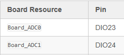
From the perspective of board resource, ADC0 is input on DIO23 and ADC1 is input on DIO24:

Board_init() is executed first after entering main();

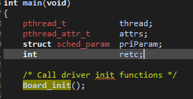
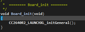
Board_init() also calls CC2640R2_LAUNCHXL_initGeneral();

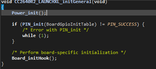
In CC2640R2_LAUNCHXL_initGeneral(); execute Power_init(); then PIN_init();

1) What does Power_init() do?Initialize power supply related resources?But there seems to be processing of the clock again. If power management is not involved in the application, can it be called directly without modifying the content?

 *  ======== Power_init ========
 */
int_fast16_t Power_init()
{
    ClockP_Params clockParams;
    uint32_t ccfgLfClkSrc;
    uint32_t timeout;

    /* if this function has already been called, just return */
    if (PowerCC26XX_module.initialized) {
        return (Power_SOK);
    }

#if defined(DeviceFamily_CC26X0R2)
    /* check to see if the JTAG_PD is on, meaning the emulator was attached during boot and */
    /* that the user is in an active debug session */
    PowerCC26XX_module.emulatorAttached = (HWREG(AON_WUC_BASE + AON_WUC_O_PWRSTAT) & AON_WUC_PWRSTAT_JTAG_PD_ON) == AON_WUC_PWRSTAT_JTAG_PD_ON;
#endif

    /* set module state field 'initialized' to true */
    PowerCC26XX_module.initialized = true;

    /* set the module state enablePolicy field */
    PowerCC26XX_module.enablePolicy = PowerCC26XX_config.enablePolicy;

    /* copy the Power policy function to module state */
    PowerCC26XX_module.policyFxn = PowerCC26XX_config.policyFxn;

    /* construct the Clock object for scheduling of wakeups */
    /* initiated and started by the power policy */
    ClockP_Params_init(&clockParams);
    clockParams.period = 0;
    clockParams.startFlag = false;
    clockParams.arg = 0;
    ClockP_construct(&PowerCC26XX_module.clockObj, &emptyClockFunc,
        0, &clockParams);

    /* construct the Clock object for XOSC_HF switching */
    /* initiated and started by Power module when activating XOSC_HF */
    ClockP_construct(&PowerCC26XX_module.xoscClockObj, &switchXOSCHFclockFunc,
        0, &clockParams);

    /* construct the Clock object for disabling LF clock quailifiers */
    /* one shot, auto start, first expires at 100 msec */
    ClockP_construct(&PowerCC26XX_module.lfClockObj, &lfClockReadyCallback,
        0, &clockParams);

    (*(PowerCC26XX_config.calibrateFxn))(PowerCC26XX_SETUP_CALIBRATE);

    DRIVERLIB_ASSERT_CURR_RELEASE();

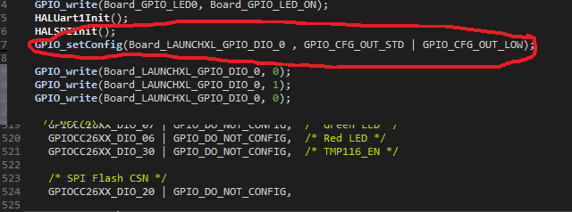
2) The BoardGpioInitTable in PIN_init() does not mention ADC0 (DIO23) and ADC1 (DIO24), where is their initialization code?

const PIN_Config BoardGpioInitTable[] = {

    CC2640R2_LAUNCHXL_PIN_RLED | PIN_GPIO_OUTPUT_EN | PIN_GPIO_LOW | PIN_PUSHPULL | PIN_DRVSTR_MAX,       /* LED initially off */
    CC2640R2_LAUNCHXL_PIN_GLED | PIN_GPIO_OUTPUT_EN | PIN_GPIO_LOW | PIN_PUSHPULL | PIN_DRVSTR_MAX,       /* LED initially off */
    CC2640R2_LAUNCHXL_PIN_BTN1 | PIN_INPUT_EN | PIN_PULLUP | PIN_IRQ_BOTHEDGES | PIN_HYSTERESIS,          /* Button is active low */
    CC2640R2_LAUNCHXL_PIN_BTN2 | PIN_INPUT_EN | PIN_PULLUP | PIN_IRQ_BOTHEDGES | PIN_HYSTERESIS,          /* Button is active low */
    CC2640R2_LAUNCHXL_SPI_FLASH_CS | PIN_GPIO_OUTPUT_EN | PIN_GPIO_HIGH | PIN_PUSHPULL | PIN_DRVSTR_MIN,  /* External flash chip select */
    CC2640R2_LAUNCHXL_UART_RX | PIN_INPUT_EN | PIN_PULLDOWN,                                              /* UART RX via debugger back channel */
    CC2640R2_LAUNCHXL_UART_TX | PIN_GPIO_OUTPUT_EN | PIN_GPIO_LOW | PIN_PUSHPULL,                         /* UART TX via debugger back channel */
    CC2640R2_LAUNCHXL_SPI0_MOSI | PIN_INPUT_EN | PIN_PULLDOWN,                                            /* SPI master out - slave in */
    CC2640R2_LAUNCHXL_SPI0_MISO | PIN_INPUT_EN | PIN_PULLDOWN,                                            /* SPI master in - slave out */
    CC2640R2_LAUNCHXL_SPI0_CLK | PIN_INPUT_EN | PIN_PULLDOWN,                                             /* SPI clock */

    PIN_TERMINATE
};

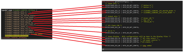
3) Here defines the pins used by SPI0:

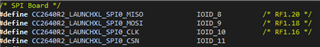
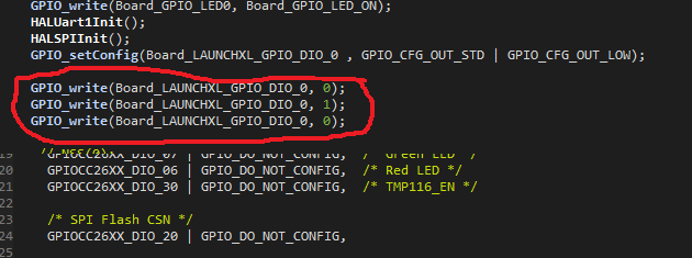
These pins are initialized here:

But how does IOID_8~IOID_11 map to the SPI0 peripheral?

4) The same PIN can map multiple functions such as digital IO, analogue input, etc. is there any docs on how to map it?

Could you help check this case? Thanks.

Best Regards,

Cherry

  • Hi Cherry,

    1) Power_init is a function that needs to be called at startup to initialize the Power Manager state.  It should not be modified.  https://dev.ti.com/tirex/explore/node?node=ABuWLDmlwjp5FCIoK75nTA__BSEc4rl__LATEST 

    2) Board_ADCx inside Board.h is defined as CC2640R2_LAUNCHXL_ADCx which exists on the CC2640R2_LAUNCHXL_ADCName and ADC_config tables in the CC2640R2_LAUNCHXL.c/h files, finally mapping to CC2640R2_LAUNCHXL_DIO2x_ANALOG in adcCC26xxHWAttrs as well.

    3) spiCC26XXDMAHWAttrs from CC2640R2_LAUNCHXL.c 

    4) It is not recommended to multiplex a pin for both analog and digital functionality during runtime.  Pin configurations are supported in the files provided.

    Regards,
    Ryan

  • Hi Ryan,

    Thanks for your support and basically all of the questions have been well resolved. 

    The customer is wondering since many of the initialization code in the program needs to be written by the user, do we have any s/w that can automatically configure the initialization code? 

    Thanks and regards,

    Cherry

  • They could migrate to the CC2642R and use SysConfig.

    Regards,
    Ryan

  • Hi Ryan,

    How to configure an IO as output?

    The sample code provided by the SDK has two functions PIN_Config and GPIO_PinConfig, and customer are not sure how to use these two functions. Could you please help provide a sample code that contains how to configure DIO0 as a GPIO output?

    Please let me know if this question is required to create a separate thread.

    Thanks and regards,

    Cherry

  • BoardGpioInitTable in CC2640R2_LAUNCHXL.c, you should make sure that IOID_0 is not already reserved elsewhere in CC2640R2_LAUNCHXL.h
    Regards,
    Ryan
  • Hi Ryan,

    The customer is configuring DIO0 in the demo item " empty " available in the SDK:

    The BoardGpioInitTable is configured as follows:

    const PIN_Config BoardGpioInitTable[] = {
    
        CC2640R2_LAUNCHXL_PIN_RLED | PIN_GPIO_OUTPUT_EN | PIN_GPIO_LOW | PIN_PUSHPULL | PIN_DRVSTR_MAX,       /* LED initially off */
        CC2640R2_LAUNCHXL_PIN_GLED | PIN_GPIO_OUTPUT_EN | PIN_GPIO_LOW | PIN_PUSHPULL | PIN_DRVSTR_MAX,       /* LED initially off */
        CC2640R2_LAUNCHXL_PIN_BTN1 | PIN_INPUT_EN | PIN_PULLUP | PIN_IRQ_BOTHEDGES | PIN_HYSTERESIS,          /* Button is active low */
        CC2640R2_LAUNCHXL_PIN_BTN2 | PIN_INPUT_EN | PIN_PULLUP | PIN_IRQ_BOTHEDGES | PIN_HYSTERESIS,          /* Button is active low */
        CC2640R2_LAUNCHXL_SPI_FLASH_CS | PIN_GPIO_OUTPUT_EN | PIN_GPIO_HIGH | PIN_PUSHPULL | PIN_DRVSTR_MIN,  /* External flash chip select */
        CC2640R2_LAUNCHXL_DIO0 |PIN_GPIO_OUTPUT_EN | PIN_PUSHPULL ,
        CC2640R2_LAUNCHXL_UART_RX | PIN_INPUT_EN | PIN_PULLDOWN,                                              /* UART RX via debugger back channel */
        CC2640R2_LAUNCHXL_UART_TX | PIN_GPIO_OUTPUT_EN | PIN_GPIO_LOW | PIN_PUSHPULL,                         /* UART TX via debugger back channel */
        CC2640R2_LAUNCHXL_SPI0_MOSI | PIN_INPUT_EN | PIN_PULLDOWN,                                            /* SPI master out - slave in */
        CC2640R2_LAUNCHXL_SPI0_MISO | PIN_INPUT_EN | PIN_PULLDOWN,                                            /* SPI master in - slave out */
        CC2640R2_LAUNCHXL_SPI0_CLK | PIN_INPUT_EN | PIN_PULLDOWN,                                             /* SPI clock */
    
        PIN_TERMINATE
    };

    Where the initialization of DIO0 has been added: 

        CC2640R2_LAUNCHXL_DIO0 |PIN_GPIO_OUTPUT_EN | PIN_PUSHPULL,

    Add the following code to empty.c, but DIO0 does not show a level change through the logic analyzer:

    GPIO_setConfig(Board_DIO0 , GPIO_CFG_OUT_STD );
    GPIO_write(Board_DIO0, 0);
    GPIO_write(Board_DIO0, 1);
    GPIO_write(Board_DIO0, 0);

    you should make sure that IOID_0 is not already reserved elsewhere in CC2640R2_LAUNCHXL.h

    It's hard for them to confirm this point.

    The customer still feel unclear to the GPIO initialization process. Although the SDK provides code, the programs that reference the SDK provide code to write do not work properly: the initialization and operation of DIO0 was written with reference to Board_GPIO_LED0, but Board_GPIO_LED0 worked properly, DIO0 didn't.

    Thanks and regards,

    Cherry

  • Did they call GPIO_init before the other GPIO functions?  They may have neglected to add the correct gpioPinConfigs entry as well.  They should consider adding PIN_GPIO_LOW to the BoardGpioInitTable's CC2640R2_LAUNCHXL_DIO0 entry and set GPIO_CFG_OUT_LOW in the GPIO_setConfig parameters.  They should also try to delay between GPIO_writes, attempt other unreserved DIOs to see whether there is any change in behavior, and confirm that their hardware does not short the connection.

    Regards,
    Ryan

  • void *mainThread(void *arg0)
    {
    /* 1 second delay */
    uint32_t time = 1;
    
    /* Call driver init functions */
    GPIO_init();
    // I2C_init();
    SPI_init();
    UART_init();

    const PIN_Config BoardGpioInitTable[] = {
    
    CC2640R2_LAUNCHXL_PIN_RLED | PIN_GPIO_OUTPUT_EN | PIN_GPIO_LOW | PIN_PUSHPULL | PIN_DRVSTR_MAX, /* LED initially off */
    CC2640R2_LAUNCHXL_PIN_GLED | PIN_GPIO_OUTPUT_EN | PIN_GPIO_LOW | PIN_PUSHPULL | PIN_DRVSTR_MAX, /* LED initially off */
    CC2640R2_LAUNCHXL_PIN_BTN1 | PIN_INPUT_EN | PIN_PULLUP | PIN_IRQ_BOTHEDGES | PIN_HYSTERESIS, /* Button is active low */
    CC2640R2_LAUNCHXL_PIN_BTN2 | PIN_INPUT_EN | PIN_PULLUP | PIN_IRQ_BOTHEDGES | PIN_HYSTERESIS, /* Button is active low */
    CC2640R2_LAUNCHXL_SPI_FLASH_CS | PIN_GPIO_OUTPUT_EN | PIN_GPIO_HIGH | PIN_PUSHPULL | PIN_DRVSTR_MIN, /* External flash chip select */
    CC2640R2_LAUNCHXL_DIO0 |PIN_GPIO_OUTPUT_EN | PIN_PUSHPULL| PIN_GPIO_LOW ,
    CC2640R2_LAUNCHXL_UART_RX | PIN_INPUT_EN | PIN_PULLDOWN, /* UART RX via debugger back channel */
    CC2640R2_LAUNCHXL_UART_TX | PIN_GPIO_OUTPUT_EN | PIN_GPIO_LOW | PIN_PUSHPULL, /* UART TX via debugger back channel */
    CC2640R2_LAUNCHXL_SPI0_MOSI | PIN_INPUT_EN | PIN_PULLDOWN, /* SPI master out - slave in */
    CC2640R2_LAUNCHXL_SPI0_MISO | PIN_INPUT_EN | PIN_PULLDOWN, /* SPI master in - slave out */
    CC2640R2_LAUNCHXL_SPI0_CLK | PIN_INPUT_EN | PIN_PULLDOWN, /* SPI clock */
    
    PIN_TERMINATE
    };

        GPIO_setConfig(Board_GPIO_LED0, GPIO_CFG_OUT_STD | GPIO_CFG_OUT_LOW);

  • Still can't control DIO0

  • I need a simple DEMO to configure IO0 as output

  • Hi werwer,

    You can take the gpiointerrupt example, apply your change to BoardGpioInitTable, and add on to gpioPinConfigs:

    GPIO_PinConfig gpioPinConfigs[] = {
        /* Input pins */
        GPIOCC26XX_DIO_13 | GPIO_DO_NOT_CONFIG,  /* Button 0 */
        GPIOCC26XX_DIO_14 | GPIO_DO_NOT_CONFIG,  /* Button 1 */
    
        GPIOCC26XX_DIO_15 | GPIO_DO_NOT_CONFIG,  /* CC2640R2_LAUNCHXL_SPI_MASTER_READY */
        GPIOCC26XX_DIO_21 | GPIO_DO_NOT_CONFIG,  /* CC2640R2_LAUNCHXL_SPI_SLAVE_READY */
    
        /* Output pins */
        GPIOCC26XX_DIO_07 | GPIO_DO_NOT_CONFIG,  /* Green LED */
        GPIOCC26XX_DIO_06 | GPIO_DO_NOT_CONFIG,  /* Red LED */
        GPIOCC26XX_DIO_30 | GPIO_DO_NOT_CONFIG,  /* TMP116_EN */
        
        GPIOCC26XX_DIO_00 | GPIO_DO_NOT_CONFIG,  // LINE ADDED
    
        /* SPI Flash CSN */
        GPIOCC26XX_DIO_20 | GPIO_DO_NOT_CONFIG,
    
        /* SD CS */
        GPIOCC26XX_DIO_21 | GPIO_DO_NOT_CONFIG,
    
        /* Sharp Display - GPIO configurations will be done in the Display files */
        GPIOCC26XX_DIO_24 | GPIO_DO_NOT_CONFIG, /* SPI chip select */
        GPIOCC26XX_DIO_22 | GPIO_DO_NOT_CONFIG, /* LCD power control */
        GPIOCC26XX_DIO_23 | GPIO_DO_NOT_CONFIG, /*LCD enable */
    
    };

    You should then be able to use GPIO_setConfig and GPIO_write for Board_DIO0 instead of Board_GPIO_LED0.  Be sure to remove any I2S code or move the definition of CC2640R2_LAUNCHXL_I2S_ADO away from IOID_0 inside CC2640R2_LAUNCHXL.h 

    Regards,
    Ryan

  • const PIN_Config BoardGpioInitTable[] = {
    
        CC2640R2_LAUNCHXL_PIN_RLED | PIN_GPIO_OUTPUT_EN | PIN_GPIO_LOW | PIN_PUSHPULL | PIN_DRVSTR_MAX,       /* LED initially off */
        CC2640R2_LAUNCHXL_PIN_GLED | PIN_GPIO_OUTPUT_EN | PIN_GPIO_LOW | PIN_PUSHPULL | PIN_DRVSTR_MAX,       /* LED initially off */
        CC2640R2_LAUNCHXL_PIN_BTN1 | PIN_INPUT_EN | PIN_PULLUP | PIN_IRQ_BOTHEDGES | PIN_HYSTERESIS,          /* Button is active low */
        CC2640R2_LAUNCHXL_PIN_BTN2 | PIN_INPUT_EN | PIN_PULLUP | PIN_IRQ_BOTHEDGES | PIN_HYSTERESIS,          /* Button is active low */
        CC2640R2_LAUNCHXL_SPI_FLASH_CS | PIN_GPIO_OUTPUT_EN | PIN_GPIO_HIGH | PIN_PUSHPULL | PIN_DRVSTR_MIN,  /* External flash chip select */
        CC2640R2_LAUNCHXL_DIO0 |PIN_GPIO_OUTPUT_EN | PIN_PUSHPULL| PIN_GPIO_LOW ,
        CC2640R2_LAUNCHXL_UART_RX | PIN_INPUT_EN | PIN_PULLDOWN,                                              /* UART RX via debugger back channel */
        CC2640R2_LAUNCHXL_UART_TX | PIN_GPIO_OUTPUT_EN | PIN_GPIO_LOW | PIN_PUSHPULL,                         /* UART TX via debugger back channel */
        CC2640R2_LAUNCHXL_SPI0_MOSI | PIN_INPUT_EN | PIN_PULLDOWN,                                            /* SPI master out - slave in */
        CC2640R2_LAUNCHXL_SPI0_MISO | PIN_INPUT_EN | PIN_PULLDOWN,                                            /* SPI master in - slave out */
        CC2640R2_LAUNCHXL_SPI0_CLK | PIN_INPUT_EN | PIN_PULLDOWN,                                             /* SPI clock */
    
        PIN_TERMINATE
    };

    GPIO_PinConfig gpioPinConfigs[] = {
        /* Input pins */
        GPIOCC26XX_DIO_13 | GPIO_DO_NOT_CONFIG,  /* Button 0 */
        GPIOCC26XX_DIO_14 | GPIO_DO_NOT_CONFIG,  /* Button 1 */
    
        GPIOCC26XX_DIO_15 | GPIO_DO_NOT_CONFIG,  /* CC2640R2_LAUNCHXL_SPI_MASTER_READY */
        GPIOCC26XX_DIO_21 | GPIO_DO_NOT_CONFIG,  /* CC2640R2_LAUNCHXL_SPI_SLAVE_READY */
    
        /* Output pins */
        GPIOCC26XX_DIO_07 | GPIO_DO_NOT_CONFIG,  /* Green LED */
        GPIOCC26XX_DIO_06 | GPIO_DO_NOT_CONFIG,  /* Red LED */
        GPIOCC26XX_DIO_30 | GPIO_DO_NOT_CONFIG,  /* TMP116_EN */
        GPIOCC26XX_DIO_00 | GPIO_DO_NOT_CONFIG,
    
        /* SPI Flash CSN */
        GPIOCC26XX_DIO_20 | GPIO_DO_NOT_CONFIG,
    
        /* SD CS */
        GPIOCC26XX_DIO_21 | GPIO_DO_NOT_CONFIG,
    
        /* Sharp Display - GPIO configurations will be done in the Display files */
        GPIOCC26XX_DIO_24 | GPIO_DO_NOT_CONFIG, /* SPI chip select */
        GPIOCC26XX_DIO_22 | GPIO_DO_NOT_CONFIG, /* LCD power control */
        GPIOCC26XX_DIO_23 | GPIO_DO_NOT_CONFIG, /*LCD enable */
    
    };
    /* I2S */
    #define CC2640R2_LAUNCHXL_I2S_ADO               IOID_22
    //#define CC2640R2_LAUNCHXL_I2S_ADO               IOID_0
    #define CC2640R2_LAUNCHXL_I2S_ADI               IOID_1
    #define CC2640R2_LAUNCHXL_I2S_BCLK              IOID_30
    #define CC2640R2_LAUNCHXL_I2S_MCLK              PIN_UNASSIGNED
    #define CC2640R2_LAUNCHXL_I2S_WCLK              IOID_29

    GPIO_init();
    // I2C_init();
    SPI_init();
    UART_init();
    
    // Watchdog_init();
    
    /* Configure the LED pin */
    GPIO_setConfig(Board_GPIO_LED0, GPIO_CFG_OUT_STD | GPIO_CFG_OUT_LOW);
    
    /* Turn on user LED */
    GPIO_write(Board_GPIO_LED0, Board_GPIO_LED_ON);
    HALUart1Init();
    HALSPIInit();
    GPIO_setConfig(Board_DIO0 , GPIO_CFG_OUT_STD | GPIO_CFG_OUT_LOW);
    // NSS(0);
    GPIO_write(Board_DIO0, 0);
    GPIO_write(Board_DIO0, 1);
    GPIO_write(Board_DIO0, 0);

  •  "empty"  Example I use,But I still can't control DIO0.

  • Hi werwer,

    I have attached the files necessary to use DIO0 as an output.

    To evaluate this, please perform the following:

    1. Import a CC2640R2 SDK example, gpiointerrupt
    2. Replace the respective files in that example, with the files attached here
    3. Remove jumper on the Green LED
    4. Add a jumper wire between Green LED and DIO0 (on Green LED side, the jumper should be attached the header which is closest to the silk screen), see image below
    5. Build and flash this example onto CC2640R2F launchpad
    6. Now you can run the example as normal, and see that the Green LED is driven from DIO0 output

    4274.Board.h

    1447.CC2640R2_LAUNCHXL.c
    /*
     * Copyright (c) 2016-2019, Texas Instruments Incorporated
     * All rights reserved.
     *
     * Redistribution and use in source and binary forms, with or without
     * modification, are permitted provided that the following conditions
     * are met:
     *
     * *  Redistributions of source code must retain the above copyright
     *    notice, this list of conditions and the following disclaimer.
     *
     * *  Redistributions in binary form must reproduce the above copyright
     *    notice, this list of conditions and the following disclaimer in the
     *    documentation and/or other materials provided with the distribution.
     *
     * *  Neither the name of Texas Instruments Incorporated nor the names of
     *    its contributors may be used to endorse or promote products derived
     *    from this software without specific prior written permission.
     *
     * THIS SOFTWARE IS PROVIDED BY THE COPYRIGHT HOLDERS AND CONTRIBUTORS "AS IS"
     * AND ANY EXPRESS OR IMPLIED WARRANTIES, INCLUDING, BUT NOT LIMITED TO,
     * THE IMPLIED WARRANTIES OF MERCHANTABILITY AND FITNESS FOR A PARTICULAR
     * PURPOSE ARE DISCLAIMED. IN NO EVENT SHALL THE COPYRIGHT OWNER OR
     * CONTRIBUTORS BE LIABLE FOR ANY DIRECT, INDIRECT, INCIDENTAL, SPECIAL,
     * EXEMPLARY, OR CONSEQUENTIAL DAMAGES (INCLUDING, BUT NOT LIMITED TO,
     * PROCUREMENT OF SUBSTITUTE GOODS OR SERVICES; LOSS OF USE, DATA, OR PROFITS;
     * OR BUSINESS INTERRUPTION) HOWEVER CAUSED AND ON ANY THEORY OF LIABILITY,
     * WHETHER IN CONTRACT, STRICT LIABILITY, OR TORT (INCLUDING NEGLIGENCE OR
     * OTHERWISE) ARISING IN ANY WAY OUT OF THE USE OF THIS SOFTWARE,
     * EVEN IF ADVISED OF THE POSSIBILITY OF SUCH DAMAGE.
     */
    
    /*
     *  ====================== CC2640R2_LAUNCHXL.c ===================================
     *  This file is responsible for setting up the board specific items for the
     *  CC2640R2_LAUNCHXL board.
     */
    
    #include <stdbool.h>
    #include <stddef.h>
    #include <stdint.h>
    
    #include <ti/devices/cc26x0r2/driverlib/ioc.h>
    #include <ti/devices/cc26x0r2/driverlib/udma.h>
    #include <ti/devices/cc26x0r2/inc/hw_ints.h>
    #include <ti/devices/cc26x0r2/inc/hw_memmap.h>
    
    #include "CC2640R2_LAUNCHXL.h"
    
    /*
     *  =============================== ADCBuf ===============================
     */
    #include <ti/drivers/ADCBuf.h>
    #include <ti/drivers/adcbuf/ADCBufCC26XX.h>
    
    ADCBufCC26XX_Object adcBufCC26xxObjects[CC2640R2_LAUNCHXL_ADCBUFCOUNT];
    
    /*
     *  This table converts a virtual adc channel into a dio and internal analogue
     *  input signal. This table is necessary for the functioning of the adcBuf
     *  driver. Comment out unused entries to save flash. Dio and internal signal
     *  pairs are hardwired. Do not remap them in the table. You may reorder entire
     *  entries. The mapping of dio and internal signals is package dependent.
     */
    const ADCBufCC26XX_AdcChannelLutEntry ADCBufCC26XX_adcChannelLut[CC2640R2_LAUNCHXL_ADCBUF0CHANNELCOUNT] = {
        {CC2640R2_LAUNCHXL_DIO23_ANALOG, ADC_COMPB_IN_AUXIO7},
        {CC2640R2_LAUNCHXL_DIO24_ANALOG, ADC_COMPB_IN_AUXIO6},
        {CC2640R2_LAUNCHXL_DIO25_ANALOG, ADC_COMPB_IN_AUXIO5},
        {CC2640R2_LAUNCHXL_DIO26_ANALOG, ADC_COMPB_IN_AUXIO4},
        {CC2640R2_LAUNCHXL_DIO27_ANALOG, ADC_COMPB_IN_AUXIO3},
        {CC2640R2_LAUNCHXL_DIO28_ANALOG, ADC_COMPB_IN_AUXIO2},
        {CC2640R2_LAUNCHXL_DIO29_ANALOG, ADC_COMPB_IN_AUXIO1},
        {CC2640R2_LAUNCHXL_DIO30_ANALOG, ADC_COMPB_IN_AUXIO0},
        {PIN_UNASSIGNED, ADC_COMPB_IN_VDDS},
        {PIN_UNASSIGNED, ADC_COMPB_IN_DCOUPL},
        {PIN_UNASSIGNED, ADC_COMPB_IN_VSS},
    };
    
    const ADCBufCC26XX_HWAttrs adcBufCC26xxHWAttrs[CC2640R2_LAUNCHXL_ADCBUFCOUNT] = {
        {
            .intPriority       = ~0,
            .swiPriority       = 0,
            .adcChannelLut     = ADCBufCC26XX_adcChannelLut,
        }
    };
    
    const ADCBuf_Config ADCBuf_config[CC2640R2_LAUNCHXL_ADCBUFCOUNT] = {
        {
            &ADCBufCC26XX_fxnTable,
            &adcBufCC26xxObjects[CC2640R2_LAUNCHXL_ADCBUF0],
            &adcBufCC26xxHWAttrs[CC2640R2_LAUNCHXL_ADCBUF0]
        },
    };
    
    const uint_least8_t ADCBuf_count = CC2640R2_LAUNCHXL_ADCBUFCOUNT;
    
    /*
     *  =============================== ADC ===============================
     */
    #include <ti/drivers/ADC.h>
    #include <ti/drivers/adc/ADCCC26XX.h>
    
    ADCCC26XX_Object adcCC26xxObjects[CC2640R2_LAUNCHXL_ADCCOUNT];
    
    const ADCCC26XX_HWAttrs adcCC26xxHWAttrs[CC2640R2_LAUNCHXL_ADCCOUNT] = {
        {
            .adcDIO              = CC2640R2_LAUNCHXL_DIO23_ANALOG,
            .adcCompBInput       = ADC_COMPB_IN_AUXIO7,
            .refSource           = ADCCC26XX_FIXED_REFERENCE,
            .samplingDuration    = ADCCC26XX_SAMPLING_DURATION_2P7_US,
            .inputScalingEnabled = true,
            .triggerSource       = ADCCC26XX_TRIGGER_MANUAL,
            .returnAdjustedVal   = false
        },
        {
            .adcDIO              = CC2640R2_LAUNCHXL_DIO24_ANALOG,
            .adcCompBInput       = ADC_COMPB_IN_AUXIO6,
            .refSource           = ADCCC26XX_FIXED_REFERENCE,
            .samplingDuration    = ADCCC26XX_SAMPLING_DURATION_2P7_US,
            .inputScalingEnabled = true,
            .triggerSource       = ADCCC26XX_TRIGGER_MANUAL,
            .returnAdjustedVal   = false
        },
        {
            .adcDIO              = CC2640R2_LAUNCHXL_DIO25_ANALOG,
            .adcCompBInput       = ADC_COMPB_IN_AUXIO5,
            .refSource           = ADCCC26XX_FIXED_REFERENCE,
            .samplingDuration    = ADCCC26XX_SAMPLING_DURATION_2P7_US,
            .inputScalingEnabled = true,
            .triggerSource       = ADCCC26XX_TRIGGER_MANUAL,
            .returnAdjustedVal   = false
        },
        {
            .adcDIO              = CC2640R2_LAUNCHXL_DIO26_ANALOG,
            .adcCompBInput       = ADC_COMPB_IN_AUXIO4,
            .refSource           = ADCCC26XX_FIXED_REFERENCE,
            .samplingDuration    = ADCCC26XX_SAMPLING_DURATION_2P7_US,
            .inputScalingEnabled = true,
            .triggerSource       = ADCCC26XX_TRIGGER_MANUAL,
            .returnAdjustedVal   = false
        },
        {
            .adcDIO              = CC2640R2_LAUNCHXL_DIO27_ANALOG,
            .adcCompBInput       = ADC_COMPB_IN_AUXIO3,
            .refSource           = ADCCC26XX_FIXED_REFERENCE,
            .samplingDuration    = ADCCC26XX_SAMPLING_DURATION_2P7_US,
            .inputScalingEnabled = true,
            .triggerSource       = ADCCC26XX_TRIGGER_MANUAL,
            .returnAdjustedVal   = false
        },
        {
            .adcDIO              = CC2640R2_LAUNCHXL_DIO28_ANALOG,
            .adcCompBInput       = ADC_COMPB_IN_AUXIO2,
            .refSource           = ADCCC26XX_FIXED_REFERENCE,
            .samplingDuration    = ADCCC26XX_SAMPLING_DURATION_2P7_US,
            .inputScalingEnabled = true,
            .triggerSource       = ADCCC26XX_TRIGGER_MANUAL,
            .returnAdjustedVal   = false
        },
        {
            .adcDIO              = CC2640R2_LAUNCHXL_DIO29_ANALOG,
            .adcCompBInput       = ADC_COMPB_IN_AUXIO1,
            .refSource           = ADCCC26XX_FIXED_REFERENCE,
            .samplingDuration    = ADCCC26XX_SAMPLING_DURATION_2P7_US,
            .inputScalingEnabled = true,
            .triggerSource       = ADCCC26XX_TRIGGER_MANUAL,
            .returnAdjustedVal   = false
        },
        {
            .adcDIO              = CC2640R2_LAUNCHXL_DIO30_ANALOG,
            .adcCompBInput       = ADC_COMPB_IN_AUXIO0,
            .refSource           = ADCCC26XX_FIXED_REFERENCE,
            .samplingDuration    = ADCCC26XX_SAMPLING_DURATION_10P9_MS,
            .inputScalingEnabled = true,
            .triggerSource       = ADCCC26XX_TRIGGER_MANUAL,
            .returnAdjustedVal   = false
        },
        {
            .adcDIO              = PIN_UNASSIGNED,
            .adcCompBInput       = ADC_COMPB_IN_DCOUPL,
            .refSource           = ADCCC26XX_FIXED_REFERENCE,
            .samplingDuration    = ADCCC26XX_SAMPLING_DURATION_2P7_US,
            .inputScalingEnabled = true,
            .triggerSource       = ADCCC26XX_TRIGGER_MANUAL,
            .returnAdjustedVal   = false
        },
        {
            .adcDIO              = PIN_UNASSIGNED,
            .adcCompBInput       = ADC_COMPB_IN_VSS,
            .refSource           = ADCCC26XX_FIXED_REFERENCE,
            .samplingDuration    = ADCCC26XX_SAMPLING_DURATION_2P7_US,
            .inputScalingEnabled = true,
            .triggerSource       = ADCCC26XX_TRIGGER_MANUAL,
            .returnAdjustedVal   = false
        },
        {
            .adcDIO              = PIN_UNASSIGNED,
            .adcCompBInput       = ADC_COMPB_IN_VDDS,
            .refSource           = ADCCC26XX_FIXED_REFERENCE,
            .samplingDuration    = ADCCC26XX_SAMPLING_DURATION_2P7_US,
            .inputScalingEnabled = true,
            .triggerSource       = ADCCC26XX_TRIGGER_MANUAL,
            .returnAdjustedVal   = false
        }
    };
    
    const ADC_Config ADC_config[CC2640R2_LAUNCHXL_ADCCOUNT] = {
        {&ADCCC26XX_fxnTable, &adcCC26xxObjects[CC2640R2_LAUNCHXL_ADC0], &adcCC26xxHWAttrs[CC2640R2_LAUNCHXL_ADC0]},
        {&ADCCC26XX_fxnTable, &adcCC26xxObjects[CC2640R2_LAUNCHXL_ADC1], &adcCC26xxHWAttrs[CC2640R2_LAUNCHXL_ADC1]},
        {&ADCCC26XX_fxnTable, &adcCC26xxObjects[CC2640R2_LAUNCHXL_ADC2], &adcCC26xxHWAttrs[CC2640R2_LAUNCHXL_ADC2]},
        {&ADCCC26XX_fxnTable, &adcCC26xxObjects[CC2640R2_LAUNCHXL_ADC3], &adcCC26xxHWAttrs[CC2640R2_LAUNCHXL_ADC3]},
        {&ADCCC26XX_fxnTable, &adcCC26xxObjects[CC2640R2_LAUNCHXL_ADC4], &adcCC26xxHWAttrs[CC2640R2_LAUNCHXL_ADC4]},
        {&ADCCC26XX_fxnTable, &adcCC26xxObjects[CC2640R2_LAUNCHXL_ADC5], &adcCC26xxHWAttrs[CC2640R2_LAUNCHXL_ADC5]},
        {&ADCCC26XX_fxnTable, &adcCC26xxObjects[CC2640R2_LAUNCHXL_ADC6], &adcCC26xxHWAttrs[CC2640R2_LAUNCHXL_ADC6]},
        {&ADCCC26XX_fxnTable, &adcCC26xxObjects[CC2640R2_LAUNCHXL_ADC7], &adcCC26xxHWAttrs[CC2640R2_LAUNCHXL_ADC7]},
        {&ADCCC26XX_fxnTable, &adcCC26xxObjects[CC2640R2_LAUNCHXL_ADCDCOUPL], &adcCC26xxHWAttrs[CC2640R2_LAUNCHXL_ADCDCOUPL]},
        {&ADCCC26XX_fxnTable, &adcCC26xxObjects[CC2640R2_LAUNCHXL_ADCVSS], &adcCC26xxHWAttrs[CC2640R2_LAUNCHXL_ADCVSS]},
        {&ADCCC26XX_fxnTable, &adcCC26xxObjects[CC2640R2_LAUNCHXL_ADCVDDS], &adcCC26xxHWAttrs[CC2640R2_LAUNCHXL_ADCVDDS]},
    };
    
    const uint_least8_t ADC_count = CC2640R2_LAUNCHXL_ADCCOUNT;
    
    /*
     *  =============================== Crypto ===============================
     */
    #include <ti/drivers/crypto/CryptoCC26XX.h>
    
    CryptoCC26XX_Object cryptoCC26XXObjects[CC2640R2_LAUNCHXL_CRYPTOCOUNT];
    
    const CryptoCC26XX_HWAttrs cryptoCC26XXHWAttrs[CC2640R2_LAUNCHXL_CRYPTOCOUNT] = {
        {
            .baseAddr       = CRYPTO_BASE,
            .powerMngrId    = PowerCC26XX_PERIPH_CRYPTO,
            .intNum         = INT_CRYPTO_RESULT_AVAIL_IRQ,
            .intPriority    = ~0,
        }
    };
    
    const CryptoCC26XX_Config CryptoCC26XX_config[CC2640R2_LAUNCHXL_CRYPTOCOUNT] = {
        {
             .object  = &cryptoCC26XXObjects[CC2640R2_LAUNCHXL_CRYPTO0],
             .hwAttrs = &cryptoCC26XXHWAttrs[CC2640R2_LAUNCHXL_CRYPTO0]
        },
    };
    
    /*
     *  =============================== AESCCM ===============================
     */
    #include <ti/drivers/AESCCM.h>
    #include <ti/drivers/aesccm/AESCCMCC26XX.h>
    
    AESCCMCC26XX_Object aesccmCC26XXObjects[CC2640R2_LAUNCHXL_AESCCMCOUNT];
    
    const AESCCMCC26XX_HWAttrs aesccmCC26XXHWAttrs[CC2640R2_LAUNCHXL_AESCCMCOUNT] = {
        {
            .intPriority       = ~0,
        }
    };
    
    const AESCCM_Config AESCCM_config[CC2640R2_LAUNCHXL_AESCCMCOUNT] = {
        {
             .object  = &aesccmCC26XXObjects[CC2640R2_LAUNCHXL_AESCCM0],
             .hwAttrs = &aesccmCC26XXHWAttrs[CC2640R2_LAUNCHXL_AESCCM0]
        },
    };
    
    const uint_least8_t AESCCM_count = CC2640R2_LAUNCHXL_AESCCMCOUNT;
    
    
    /*
     *  =============================== AESGCM ===============================
     */
    #include <ti/drivers/AESGCM.h>
    #include <ti/drivers/aesgcm/AESGCMCC26XX.h>
    
    AESGCMCC26XX_Object aesgcmCC26XXObjects[CC2640R2_LAUNCHXL_AESGCMCOUNT];
    
    const AESGCMCC26XX_HWAttrs aesgcmCC26XXHWAttrs[CC2640R2_LAUNCHXL_AESGCMCOUNT] = {
        {
            .intPriority       = ~0,
        }
    };
    
    const AESGCM_Config AESGCM_config[CC2640R2_LAUNCHXL_AESGCMCOUNT] = {
        {
             .object  = &aesgcmCC26XXObjects[CC2640R2_LAUNCHXL_AESGCM0],
             .hwAttrs = &aesgcmCC26XXHWAttrs[CC2640R2_LAUNCHXL_AESGCM0]
        },
    };
    
    const uint_least8_t AESGCM_count = CC2640R2_LAUNCHXL_AESGCMCOUNT;
    
    /*
     *  =============================== AESCBC ===============================
     */
    #include <ti/drivers/AESCBC.h>
    #include <ti/drivers/aescbc/AESCBCCC26XX.h>
    
    AESCBCCC26XX_Object aescbcCC26XXObjects[CC2640R2_LAUNCHXL_AESCBCCOUNT];
    
    const AESCBCCC26XX_HWAttrs aescbcCC26XXHWAttrs[CC2640R2_LAUNCHXL_AESCBCCOUNT] = {
        {
            .intPriority       = ~0,
        }
    };
    
    const AESCBC_Config AESCBC_config[CC2640R2_LAUNCHXL_AESCBCCOUNT] = {
        {
             .object  = &aescbcCC26XXObjects[CC2640R2_LAUNCHXL_AESCBC0],
             .hwAttrs = &aescbcCC26XXHWAttrs[CC2640R2_LAUNCHXL_AESCBC0]
        },
    };
    
    const uint_least8_t AESCBC_count = CC2640R2_LAUNCHXL_AESCBCCOUNT;
    
    /*
     *  =============================== AESCTR ===============================
     */
    #include <ti/drivers/AESCTR.h>
    #include <ti/drivers/aesctr/AESCTRCC26XX.h>
    
    AESCTRCC26XX_Object aesctrCC26XXObjects[CC2640R2_LAUNCHXL_AESCTRCOUNT];
    
    const AESCTRCC26XX_HWAttrs aesctrCC26XXHWAttrs[CC2640R2_LAUNCHXL_AESCTRCOUNT] = {
        {
            .intPriority       = ~0,
        }
    };
    
    const AESCTR_Config AESCTR_config[CC2640R2_LAUNCHXL_AESCTRCOUNT] = {
        {
             .object  = &aesctrCC26XXObjects[CC2640R2_LAUNCHXL_AESCTR0],
             .hwAttrs = &aesctrCC26XXHWAttrs[CC2640R2_LAUNCHXL_AESCTR0]
        },
    };
    
    const uint_least8_t AESCTR_count = CC2640R2_LAUNCHXL_AESCTRCOUNT;
    
    /*
     *  =============================== AESECB ===============================
     */
    #include <ti/drivers/AESECB.h>
    #include <ti/drivers/aesecb/AESECBCC26XX.h>
    
    AESECBCC26XX_Object aesecbCC26XXObjects[CC2640R2_LAUNCHXL_AESECBCOUNT];
    
    const AESECBCC26XX_HWAttrs aesecbCC26XXHWAttrs[CC2640R2_LAUNCHXL_AESECBCOUNT] = {
        {
            .intPriority       = ~0,
        }
    };
    
    const AESECB_Config AESECB_config[CC2640R2_LAUNCHXL_AESECBCOUNT] = {
        {
             .object  = &aesecbCC26XXObjects[CC2640R2_LAUNCHXL_AESECB0],
             .hwAttrs = &aesecbCC26XXHWAttrs[CC2640R2_LAUNCHXL_AESECB0]
        },
    };
    
    const uint_least8_t AESECB_count = CC2640R2_LAUNCHXL_AESECBCOUNT;
    
    /*
     *  =============================== AESCTRDRBG ===============================
     */
    #include <ti/drivers/AESCTRDRBG.h>
    #include <ti/drivers/aesctrdrbg/AESCTRDRBGXX.h>
    
    AESCTRDRBGXX_Object aesctrdrbgXXObjects[CC2640R2_LAUNCHXL_AESCTRDRBGCOUNT];
    
    const AESCTRDRBGXX_HWAttrs aesctrdrbgXXHWAttrs[CC2640R2_LAUNCHXL_AESCTRDRBGCOUNT] = {
        {
            .aesctrIndex       = CC2640R2_LAUNCHXL_AESCTR0,
        }
    };
    
    const AESCTRDRBG_Config AESCTRDRBG_config[CC2640R2_LAUNCHXL_AESCTRDRBGCOUNT] = {
        {
             .object  = &aesctrdrbgXXObjects[CC2640R2_LAUNCHXL_AESCTRDRBG0],
             .hwAttrs = &aesctrdrbgXXHWAttrs[CC2640R2_LAUNCHXL_AESCTRDRBG0]
        },
    };
    
    const uint_least8_t AESCTRDRBG_count = CC2640R2_LAUNCHXL_AESCTRDRBGCOUNT;
    
    /*
     *  =============================== TRNG ===============================
     */
    #include <ti/drivers/TRNG.h>
    #include <ti/drivers/trng/TRNGCC26XX.h>
    
    TRNGCC26XX_Object trngCC26XXObjects[CC2640R2_LAUNCHXL_TRNGCOUNT];
    
    const TRNGCC26XX_HWAttrs trngCC26X2HWAttrs[CC2640R2_LAUNCHXL_TRNGCOUNT] = {
        {
            .intPriority       = ~0,
            .swiPriority       = 0,
            .samplesPerCycle   = 240000,
        }
    };
    
    const TRNG_Config TRNG_config[CC2640R2_LAUNCHXL_TRNGCOUNT] = {
        {
             .object  = &trngCC26XXObjects[CC2640R2_LAUNCHXL_TRNG0],
             .hwAttrs = &trngCC26X2HWAttrs[CC2640R2_LAUNCHXL_TRNG0]
        },
    };
    
    const uint_least8_t TRNG_count = CC2640R2_LAUNCHXL_TRNGCOUNT;
    
    
    /*
     *  =============================== Display ===============================
     */
    #include <ti/display/Display.h>
    #include <ti/display/DisplayUart.h>
    #include <ti/display/DisplaySharp.h>
    
    #ifndef BOARD_DISPLAY_UART_STRBUF_SIZE
    #define BOARD_DISPLAY_UART_STRBUF_SIZE    128
    #endif
    
    /* This value can be changed to 96 for use with the 430BOOST-SHARP96 BoosterPack. */
    #define BOARD_DISPLAY_SHARP_SIZE    128
    
    DisplayUart_Object     displayUartObject;
    DisplaySharp_Object    displaySharpObject;
    
    static char uartStringBuf[BOARD_DISPLAY_UART_STRBUF_SIZE];
    static uint_least8_t sharpDisplayBuf[BOARD_DISPLAY_SHARP_SIZE * BOARD_DISPLAY_SHARP_SIZE / 8];
    
    const DisplayUart_HWAttrs displayUartHWAttrs = {
        .uartIdx      = CC2640R2_LAUNCHXL_UART0,
        .baudRate     = 115200,
        .mutexTimeout = (unsigned int)(-1),
        .strBuf       = uartStringBuf,
        .strBufLen    = BOARD_DISPLAY_UART_STRBUF_SIZE,
    };
    
    const DisplaySharp_HWAttrsV1 displaySharpHWattrs = {
        .spiIndex    = CC2640R2_LAUNCHXL_SPI0,
        .csPin       = CC2640R2_LAUNCHXL_GPIO_LCD_CS,
        .powerPin    = CC2640R2_LAUNCHXL_GPIO_LCD_POWER,
        .enablePin   = CC2640R2_LAUNCHXL_GPIO_LCD_ENABLE,
        .pixelWidth  = BOARD_DISPLAY_SHARP_SIZE,
        .pixelHeight = BOARD_DISPLAY_SHARP_SIZE,
        .displayBuf  = sharpDisplayBuf,
    };
    
    #ifndef BOARD_DISPLAY_USE_UART
    #define BOARD_DISPLAY_USE_UART 1
    #endif
    #ifndef BOARD_DISPLAY_USE_UART_ANSI
    #define BOARD_DISPLAY_USE_UART_ANSI 0
    #endif
    #ifndef BOARD_DISPLAY_USE_LCD
    #define BOARD_DISPLAY_USE_LCD 0
    #endif
    
    /*
     * This #if/#else is needed to workaround a problem with the
     * IAR compiler. The IAR compiler doesn't like the empty array
     * initialization. (IAR Error[Pe1345])
     */
    #if (BOARD_DISPLAY_USE_UART || BOARD_DISPLAY_USE_LCD)
    
    const Display_Config Display_config[] = {
    #if (BOARD_DISPLAY_USE_UART)
        {
    #  if (BOARD_DISPLAY_USE_UART_ANSI)
            .fxnTablePtr = &DisplayUartAnsi_fxnTable,
    #  else /* Default to minimal UART with no cursor placement */
            .fxnTablePtr = &DisplayUartMin_fxnTable,
    #  endif
            .object      = &displayUartObject,
            .hwAttrs     = &displayUartHWAttrs,
        },
    #endif
    #if (BOARD_DISPLAY_USE_LCD)
        {
            .fxnTablePtr = &DisplaySharp_fxnTable,
            .object      = &displaySharpObject,
            .hwAttrs     = &displaySharpHWattrs
        },
    #endif
    };
    
    const uint_least8_t Display_count = sizeof(Display_config) / sizeof(Display_Config);
    
    #else
    
    const Display_Config *Display_config = NULL;
    const uint_least8_t Display_count = 0;
    
    #endif /* (BOARD_DISPLAY_USE_UART || BOARD_DISPLAY_USE_LCD) */
    
    /*
     *  =============================== GPIO ===============================
     */
    #include <ti/drivers/GPIO.h>
    #include <ti/drivers/gpio/GPIOCC26XX.h>
    
    /*
     * Array of Pin configurations
     * NOTE: The order of the pin configurations must coincide with what was
     *       defined in CC2640R2_LAUNCHXL.h
     * NOTE: Pins not used for interrupts should be placed at the end of the
     *       array. Callback entries can be omitted from callbacks array to
     *       reduce memory usage.
     */
    GPIO_PinConfig gpioPinConfigs[] = {
        /* Input pins */
        GPIOCC26XX_DIO_13 | GPIO_DO_NOT_CONFIG,  /* Button 0 */
        GPIOCC26XX_DIO_14 | GPIO_DO_NOT_CONFIG,  /* Button 1 */
    
        GPIOCC26XX_DIO_15 | GPIO_DO_NOT_CONFIG,  /* CC2640R2_LAUNCHXL_SPI_MASTER_READY */
        GPIOCC26XX_DIO_21 | GPIO_DO_NOT_CONFIG,  /* CC2640R2_LAUNCHXL_SPI_SLAVE_READY */
    
        /* Output pins */
        GPIOCC26XX_DIO_07 | GPIO_DO_NOT_CONFIG,  /* Green LED */
        GPIOCC26XX_DIO_06 | GPIO_DO_NOT_CONFIG,  /* Red LED */
        GPIOCC26XX_DIO_30 | GPIO_DO_NOT_CONFIG,  /* TMP116_EN */
    
        /* SPI Flash CSN */
        GPIOCC26XX_DIO_20 | GPIO_DO_NOT_CONFIG,
    
        /* SD CS */
        GPIOCC26XX_DIO_21 | GPIO_DO_NOT_CONFIG,
    
        /* Sharp Display - GPIO configurations will be done in the Display files */
        GPIOCC26XX_DIO_24 | GPIO_DO_NOT_CONFIG, /* SPI chip select */
        GPIOCC26XX_DIO_22 | GPIO_DO_NOT_CONFIG, /* LCD power control */
        GPIOCC26XX_DIO_23 | GPIO_DO_NOT_CONFIG, /*LCD enable */
    
        GPIOCC26XX_DIO_00 | GPIO_DO_NOT_CONFIG, // toby added
    
    };
    
    /*
     * Array of callback function pointers
     * NOTE: The order of the pin configurations must coincide with what was
     *       defined in CC2640R2_LAUNCH.h
     * NOTE: Pins not used for interrupts can be omitted from callbacks array to
     *       reduce memory usage (if placed at end of gpioPinConfigs array).
     */
    GPIO_CallbackFxn gpioCallbackFunctions[] = {
        NULL,  /* Button 0 */
        NULL,  /* Button 1 */
        NULL,  /* CC2640R2_LAUNCHXL_SPI_MASTER_READY */
        NULL,  /* CC2640R2_LAUNCHXL_SPI_SLAVE_READY */
    };
    
    const GPIOCC26XX_Config GPIOCC26XX_config = {
        .pinConfigs         = (GPIO_PinConfig *)gpioPinConfigs,
        .callbacks          = (GPIO_CallbackFxn *)gpioCallbackFunctions,
        .numberOfPinConfigs = CC2640R2_LAUNCHXL_GPIOCOUNT,
        .numberOfCallbacks  = sizeof(gpioCallbackFunctions)/sizeof(GPIO_CallbackFxn),
        .intPriority        = (~0)
    };
    
    /*
     *  =============================== GPTimer ===============================
     *  Remove unused entries to reduce flash usage both in Board.c and Board.h
     */
    #include <ti/drivers/timer/GPTimerCC26XX.h>
    
    GPTimerCC26XX_Object gptimerCC26XXObjects[CC2640R2_LAUNCHXL_GPTIMERCOUNT];
    
    const GPTimerCC26XX_HWAttrs gptimerCC26xxHWAttrs[CC2640R2_LAUNCHXL_GPTIMERPARTSCOUNT] = {
        { .baseAddr = GPT0_BASE, .intNum = INT_GPT0A, .intPriority = (~0), .powerMngrId = PowerCC26XX_PERIPH_GPT0, .pinMux = GPT_PIN_0A, },
        { .baseAddr = GPT0_BASE, .intNum = INT_GPT0B, .intPriority = (~0), .powerMngrId = PowerCC26XX_PERIPH_GPT0, .pinMux = GPT_PIN_0B, },
        { .baseAddr = GPT1_BASE, .intNum = INT_GPT1A, .intPriority = (~0), .powerMngrId = PowerCC26XX_PERIPH_GPT1, .pinMux = GPT_PIN_1A, },
        { .baseAddr = GPT1_BASE, .intNum = INT_GPT1B, .intPriority = (~0), .powerMngrId = PowerCC26XX_PERIPH_GPT1, .pinMux = GPT_PIN_1B, },
        { .baseAddr = GPT2_BASE, .intNum = INT_GPT2A, .intPriority = (~0), .powerMngrId = PowerCC26XX_PERIPH_GPT2, .pinMux = GPT_PIN_2A, },
        { .baseAddr = GPT2_BASE, .intNum = INT_GPT2B, .intPriority = (~0), .powerMngrId = PowerCC26XX_PERIPH_GPT2, .pinMux = GPT_PIN_2B, },
        { .baseAddr = GPT3_BASE, .intNum = INT_GPT3A, .intPriority = (~0), .powerMngrId = PowerCC26XX_PERIPH_GPT3, .pinMux = GPT_PIN_3A, },
        { .baseAddr = GPT3_BASE, .intNum = INT_GPT3B, .intPriority = (~0), .powerMngrId = PowerCC26XX_PERIPH_GPT3, .pinMux = GPT_PIN_3B, },
    };
    
    const GPTimerCC26XX_Config GPTimerCC26XX_config[CC2640R2_LAUNCHXL_GPTIMERPARTSCOUNT] = {
        { &gptimerCC26XXObjects[CC2640R2_LAUNCHXL_GPTIMER0], &gptimerCC26xxHWAttrs[CC2640R2_LAUNCHXL_GPTIMER0A], GPT_A },
        { &gptimerCC26XXObjects[CC2640R2_LAUNCHXL_GPTIMER0], &gptimerCC26xxHWAttrs[CC2640R2_LAUNCHXL_GPTIMER0B], GPT_B },
        { &gptimerCC26XXObjects[CC2640R2_LAUNCHXL_GPTIMER1], &gptimerCC26xxHWAttrs[CC2640R2_LAUNCHXL_GPTIMER1A], GPT_A },
        { &gptimerCC26XXObjects[CC2640R2_LAUNCHXL_GPTIMER1], &gptimerCC26xxHWAttrs[CC2640R2_LAUNCHXL_GPTIMER1B], GPT_B },
        { &gptimerCC26XXObjects[CC2640R2_LAUNCHXL_GPTIMER2], &gptimerCC26xxHWAttrs[CC2640R2_LAUNCHXL_GPTIMER2A], GPT_A },
        { &gptimerCC26XXObjects[CC2640R2_LAUNCHXL_GPTIMER2], &gptimerCC26xxHWAttrs[CC2640R2_LAUNCHXL_GPTIMER2B], GPT_B },
        { &gptimerCC26XXObjects[CC2640R2_LAUNCHXL_GPTIMER3], &gptimerCC26xxHWAttrs[CC2640R2_LAUNCHXL_GPTIMER3A], GPT_A },
        { &gptimerCC26XXObjects[CC2640R2_LAUNCHXL_GPTIMER3], &gptimerCC26xxHWAttrs[CC2640R2_LAUNCHXL_GPTIMER3B], GPT_B },
    };
    
    /*
     *  =============================== I2C ===============================
    */
    #include <ti/drivers/I2C.h>
    #include <ti/drivers/i2c/I2CCC26XX.h>
    
    I2CCC26XX_Object i2cCC26xxObjects[CC2640R2_LAUNCHXL_I2CCOUNT];
    
    const I2CCC26XX_HWAttrsV1 i2cCC26xxHWAttrs[CC2640R2_LAUNCHXL_I2CCOUNT] = {
        {
            .baseAddr    = I2C0_BASE,
            .powerMngrId = PowerCC26XX_PERIPH_I2C0,
            .intNum      = INT_I2C_IRQ,
            .intPriority = ~0,
            .swiPriority = 0,
            .sdaPin      = CC2640R2_LAUNCHXL_I2C0_SDA0,
            .sclPin      = CC2640R2_LAUNCHXL_I2C0_SCL0,
        }
    };
    
    const I2C_Config I2C_config[CC2640R2_LAUNCHXL_I2CCOUNT] = {
        {
            .fxnTablePtr = &I2CCC26XX_fxnTable,
            .object      = &i2cCC26xxObjects[CC2640R2_LAUNCHXL_I2C0],
            .hwAttrs     = &i2cCC26xxHWAttrs[CC2640R2_LAUNCHXL_I2C0]
        },
    };
    
    const uint_least8_t I2C_count = CC2640R2_LAUNCHXL_I2CCOUNT;
    
    /*
     *  =============================== I2S ===============================
    */
    #include <ti/drivers/I2S.h>
    #include <ti/drivers/i2s/I2SCC26XX.h>
    
    I2SCC26XX_Object i2sCC26XXObjects[CC2640R2_LAUNCHXL_I2SCOUNT];
    
    const I2SCC26XX_HWAttrs i2sCC26XXHWAttrs[CC2640R2_LAUNCHXL_I2SCOUNT] = {
        {
            .pinSD1      =  CC2640R2_LAUNCHXL_I2S_ADI,
            .pinSD0      =  CC2640R2_LAUNCHXL_I2S_ADO,
            .pinSCK      =  CC2640R2_LAUNCHXL_I2S_BCLK,
            .pinMCLK     =  CC2640R2_LAUNCHXL_I2S_MCLK,
            .pinWS       =  CC2640R2_LAUNCHXL_I2S_WCLK,
            .intPriority = ~0,
        }
    };
    
    const I2S_Config I2S_config[CC2640R2_LAUNCHXL_I2SCOUNT] = {
        {
            .object      = &i2sCC26XXObjects[CC2640R2_LAUNCHXL_I2S0],
            .hwAttrs     = &i2sCC26XXHWAttrs[CC2640R2_LAUNCHXL_I2S0]
        },
    };
    
    const uint_least8_t I2S_count = CC2640R2_LAUNCHXL_I2SCOUNT;
    
    /*
     *  =============================== NVS ===============================
     */
    #include <ti/drivers/NVS.h>
    #include <ti/drivers/nvs/NVSSPI25X.h>
    #include <ti/drivers/nvs/NVSCC26XX.h>
    
    #define NVS_REGIONS_BASE 0x1A000
    #define SECTORSIZE       0x1000
    #define REGIONSIZE       (SECTORSIZE * 4)
    
    #ifndef Board_EXCLUDE_NVS_INTERNAL_FLASH
    
    /*
     * Reserve flash sectors for NVS driver use by placing an uninitialized byte
     * array at the desired flash address.
     */
    #if defined(__TI_COMPILER_VERSION__)
    
    /*
     * Place uninitialized array at NVS_REGIONS_BASE
     */
    #pragma LOCATION(flashBuf, NVS_REGIONS_BASE);
    #pragma NOINIT(flashBuf);
    static char flashBuf[REGIONSIZE];
    
    #elif defined(__IAR_SYSTEMS_ICC__)
    
    /*
     * Place uninitialized array at NVS_REGIONS_BASE
     */
    static __no_init char flashBuf[REGIONSIZE] @ NVS_REGIONS_BASE;
    
    #elif defined(__GNUC__)
    
    /*
     * Place the flash buffers in the .nvs section created in the gcc linker file.
     * The .nvs section enforces alignment on a sector boundary but may
     * be placed anywhere in flash memory.  If desired the .nvs section can be set
     * to a fixed address by changing the following in the gcc linker file:
     *
     * .nvs (FIXED_FLASH_ADDR) (NOLOAD) : AT (FIXED_FLASH_ADDR) {
     *      *(.nvs)
     * } > REGION_TEXT
     */
    __attribute__ ((section (".nvs")))
    static char flashBuf[REGIONSIZE];
    
    #endif
    
    /* Allocate objects for NVS Internal Regions */
    NVSCC26XX_Object nvsCC26xxObjects[1];
    
    /* Hardware attributes for NVS Internal Regions */
    const NVSCC26XX_HWAttrs nvsCC26xxHWAttrs[1] = {
        {
            .regionBase = (void *)flashBuf,
            .regionSize = REGIONSIZE,
        },
    };
    
    #endif /* Board_EXCLUDE_NVS_INTERNAL_FLASH */
    
    #ifndef Board_EXCLUDE_NVS_EXTERNAL_FLASH
    
    #define SPISECTORSIZE    0x1000
    #define SPIREGIONSIZE    (SPISECTORSIZE * 32)
    #define VERIFYBUFSIZE    64
    
    static uint8_t verifyBuf[VERIFYBUFSIZE];
    
    /* Allocate objects for NVS External Regions */
    NVSSPI25X_Object nvsSPI25XObjects[1];
    
    /* Hardware attributes for NVS External Regions */
    const NVSSPI25X_HWAttrs nvsSPI25XHWAttrs[1] = {
        {
            .regionBaseOffset = 0,
            .regionSize = SPIREGIONSIZE,
            .sectorSize = SPISECTORSIZE,
            .verifyBuf = verifyBuf,
            .verifyBufSize = VERIFYBUFSIZE,
            .spiHandle = NULL,
            .spiIndex = 0,
            .spiBitRate = 4000000,
            .spiCsnGpioIndex = CC2640R2_LAUNCHXL_GPIO_SPI_FLASH_CS,
            .statusPollDelayUs = 100,
        },
    };
    
    #endif /* Board_EXCLUDE_NVS_EXTERNAL_FLASH */
    
    /* NVS Region index 0 and 1 refer to NVS and NVS SPI respectively */
    const NVS_Config NVS_config[CC2640R2_LAUNCHXL_NVSCOUNT] = {
    #ifndef Board_EXCLUDE_NVS_INTERNAL_FLASH
        {
            .fxnTablePtr = &NVSCC26XX_fxnTable,
            .object = &nvsCC26xxObjects[0],
            .hwAttrs = &nvsCC26xxHWAttrs[0],
        },
    #endif
    #ifndef Board_EXCLUDE_NVS_EXTERNAL_FLASH
        {
            .fxnTablePtr = &NVSSPI25X_fxnTable,
            .object = &nvsSPI25XObjects[0],
            .hwAttrs = &nvsSPI25XHWAttrs[0],
        },
    #endif
    };
    
    const uint_least8_t NVS_count = CC2640R2_LAUNCHXL_NVSCOUNT;
    
    /*
     *  =============================== PIN ===============================
     */
    #include <ti/drivers/PIN.h>
    #include <ti/drivers/pin/PINCC26XX.h>
    
    const PIN_Config BoardGpioInitTable[] = {
    
        CC2640R2_LAUNCHXL_PIN_RLED | PIN_GPIO_OUTPUT_EN | PIN_GPIO_LOW | PIN_PUSHPULL | PIN_DRVSTR_MAX,       /* LED initially off */
        CC2640R2_LAUNCHXL_PIN_GLED | PIN_GPIO_OUTPUT_EN | PIN_GPIO_LOW | PIN_PUSHPULL | PIN_DRVSTR_MAX,       /* LED initially off */
        CC2640R2_LAUNCHXL_PIN_BTN1 | PIN_INPUT_EN | PIN_PULLUP | PIN_IRQ_BOTHEDGES | PIN_HYSTERESIS,          /* Button is active low */
        CC2640R2_LAUNCHXL_PIN_BTN2 | PIN_INPUT_EN | PIN_PULLUP | PIN_IRQ_BOTHEDGES | PIN_HYSTERESIS,          /* Button is active low */
        CC2640R2_LAUNCHXL_SPI_FLASH_CS | PIN_GPIO_OUTPUT_EN | PIN_GPIO_HIGH | PIN_PUSHPULL | PIN_DRVSTR_MIN,  /* External flash chip select */
        CC2640R2_LAUNCHXL_UART_RX | PIN_INPUT_EN | PIN_PULLDOWN,                                              /* UART RX via debugger back channel */
        CC2640R2_LAUNCHXL_UART_TX | PIN_GPIO_OUTPUT_EN | PIN_GPIO_LOW | PIN_PUSHPULL,                         /* UART TX via debugger back channel */
        CC2640R2_LAUNCHXL_SPI0_MOSI | PIN_INPUT_EN | PIN_PULLDOWN,                                            /* SPI master out - slave in */
        CC2640R2_LAUNCHXL_SPI0_MISO | PIN_INPUT_EN | PIN_PULLDOWN,                                            /* SPI master in - slave out */
        CC2640R2_LAUNCHXL_SPI0_CLK | PIN_INPUT_EN | PIN_PULLDOWN,                                             /* SPI clock */
    
        PIN_TERMINATE
    };
    
    const PINCC26XX_HWAttrs PINCC26XX_hwAttrs = {
        .intPriority = ~0,
        .swiPriority = 0
    };
    
    /*
     *  =============================== Power ===============================
     */
    #include <ti/drivers/Power.h>
    #include <ti/drivers/power/PowerCC26XX.h>
    
    const PowerCC26XX_Config PowerCC26XX_config = {
        .policyInitFxn      = NULL,
        .policyFxn          = &PowerCC26XX_standbyPolicy,
        .calibrateFxn       = &PowerCC26XX_calibrate,
        .enablePolicy       = true,
        .calibrateRCOSC_LF  = true,
        .calibrateRCOSC_HF  = true,
    };
    
    /*
     *  =============================== PWM ===============================
     *  Remove unused entries to reduce flash usage both in Board.c and Board.h
     */
    #include <ti/drivers/PWM.h>
    #include <ti/drivers/pwm/PWMTimerCC26XX.h>
    
    PWMTimerCC26XX_Object pwmtimerCC26xxObjects[CC2640R2_LAUNCHXL_PWMCOUNT];
    
    const PWMTimerCC26XX_HwAttrs pwmtimerCC26xxHWAttrs[CC2640R2_LAUNCHXL_PWMCOUNT] = {
        { .pwmPin = CC2640R2_LAUNCHXL_PWMPIN0, .gpTimerUnit = CC2640R2_LAUNCHXL_GPTIMER0A },
        { .pwmPin = CC2640R2_LAUNCHXL_PWMPIN1, .gpTimerUnit = CC2640R2_LAUNCHXL_GPTIMER0B },
        { .pwmPin = CC2640R2_LAUNCHXL_PWMPIN2, .gpTimerUnit = CC2640R2_LAUNCHXL_GPTIMER1A },
        { .pwmPin = CC2640R2_LAUNCHXL_PWMPIN3, .gpTimerUnit = CC2640R2_LAUNCHXL_GPTIMER1B },
        { .pwmPin = CC2640R2_LAUNCHXL_PWMPIN4, .gpTimerUnit = CC2640R2_LAUNCHXL_GPTIMER2A },
        { .pwmPin = CC2640R2_LAUNCHXL_PWMPIN5, .gpTimerUnit = CC2640R2_LAUNCHXL_GPTIMER2B },
        { .pwmPin = CC2640R2_LAUNCHXL_PWMPIN6, .gpTimerUnit = CC2640R2_LAUNCHXL_GPTIMER3A },
        { .pwmPin = CC2640R2_LAUNCHXL_PWMPIN7, .gpTimerUnit = CC2640R2_LAUNCHXL_GPTIMER3B },
    };
    
    const PWM_Config PWM_config[CC2640R2_LAUNCHXL_PWMCOUNT] = {
        { &PWMTimerCC26XX_fxnTable, &pwmtimerCC26xxObjects[CC2640R2_LAUNCHXL_PWM0], &pwmtimerCC26xxHWAttrs[CC2640R2_LAUNCHXL_PWM0] },
        { &PWMTimerCC26XX_fxnTable, &pwmtimerCC26xxObjects[CC2640R2_LAUNCHXL_PWM1], &pwmtimerCC26xxHWAttrs[CC2640R2_LAUNCHXL_PWM1] },
        { &PWMTimerCC26XX_fxnTable, &pwmtimerCC26xxObjects[CC2640R2_LAUNCHXL_PWM2], &pwmtimerCC26xxHWAttrs[CC2640R2_LAUNCHXL_PWM2] },
        { &PWMTimerCC26XX_fxnTable, &pwmtimerCC26xxObjects[CC2640R2_LAUNCHXL_PWM3], &pwmtimerCC26xxHWAttrs[CC2640R2_LAUNCHXL_PWM3] },
        { &PWMTimerCC26XX_fxnTable, &pwmtimerCC26xxObjects[CC2640R2_LAUNCHXL_PWM4], &pwmtimerCC26xxHWAttrs[CC2640R2_LAUNCHXL_PWM4] },
        { &PWMTimerCC26XX_fxnTable, &pwmtimerCC26xxObjects[CC2640R2_LAUNCHXL_PWM5], &pwmtimerCC26xxHWAttrs[CC2640R2_LAUNCHXL_PWM5] },
        { &PWMTimerCC26XX_fxnTable, &pwmtimerCC26xxObjects[CC2640R2_LAUNCHXL_PWM6], &pwmtimerCC26xxHWAttrs[CC2640R2_LAUNCHXL_PWM6] },
        { &PWMTimerCC26XX_fxnTable, &pwmtimerCC26xxObjects[CC2640R2_LAUNCHXL_PWM7], &pwmtimerCC26xxHWAttrs[CC2640R2_LAUNCHXL_PWM7] },
    };
    
    const uint_least8_t PWM_count = CC2640R2_LAUNCHXL_PWMCOUNT;
    
    /*
     *  =============================== RF Driver ===============================
     */
    #include <ti/drivers/rf/RF.h>
    
    const RFCC26XX_HWAttrsV2 RFCC26XX_hwAttrs = {
        .hwiPriority        = ~0,       /* Lowest HWI priority */
        .swiPriority        = 0,        /* Lowest SWI priority */
        .xoscHfAlwaysNeeded = true,     /* Keep XOSC dependency while in standby */
        .globalCallback     = NULL,     /* No board specific callback */
        .globalEventMask    = 0         /* No events subscribed to */
    };
    
    /*
     *  =============================== SD ===============================
     */
    #include <ti/drivers/SD.h>
    #include <ti/drivers/sd/SDSPI.h>
    
    SDSPI_Object sdspiObjects[CC2640R2_LAUNCHXL_SDCOUNT];
    
    const SDSPI_HWAttrs sdspiHWAttrs[CC2640R2_LAUNCHXL_SDCOUNT] = {
        {
            .spiIndex = CC2640R2_LAUNCHXL_SPI0,
            .spiCsGpioIndex = CC2640R2_LAUNCHXL_SDSPI_CS
        }
    };
    
    const SD_Config SD_config[CC2640R2_LAUNCHXL_SDCOUNT] = {
        {
            .fxnTablePtr = &SDSPI_fxnTable,
            .object = &sdspiObjects[CC2640R2_LAUNCHXL_SDSPI0],
            .hwAttrs = &sdspiHWAttrs[CC2640R2_LAUNCHXL_SDSPI0]
        },
    };
    
    const uint_least8_t SD_count = CC2640R2_LAUNCHXL_SDCOUNT;
    
    /*
     *  =============================== SPI DMA ===============================
     */
    #include <ti/drivers/SPI.h>
    #include <ti/drivers/spi/SPICC26XXDMA.h>
    
    SPICC26XXDMA_Object spiCC26XXDMAObjects[CC2640R2_LAUNCHXL_SPICOUNT];
    
    /*
     * NOTE: The SPI instances below can be used by the SD driver to communicate
     * with a SD card via SPI.  The 'defaultTxBufValue' fields below are set to 0xFF
     * to satisfy the SDSPI driver requirement.
     */
    const SPICC26XXDMA_HWAttrsV1 spiCC26XXDMAHWAttrs[CC2640R2_LAUNCHXL_SPICOUNT] = {
        {
            .baseAddr           = SSI0_BASE,
            .intNum             = INT_SSI0_COMB,
            .intPriority        = ~0,
            .swiPriority        = 0,
            .powerMngrId        = PowerCC26XX_PERIPH_SSI0,
            .defaultTxBufValue  = 0xFF,
            .rxChannelBitMask   = 1<<UDMA_CHAN_SSI0_RX,
            .txChannelBitMask   = 1<<UDMA_CHAN_SSI0_TX,
            .mosiPin            = CC2640R2_LAUNCHXL_SPI0_MOSI,
            .misoPin            = CC2640R2_LAUNCHXL_SPI0_MISO,
            .clkPin             = CC2640R2_LAUNCHXL_SPI0_CLK,
            .csnPin             = CC2640R2_LAUNCHXL_SPI0_CSN,
            .minDmaTransferSize = 10
        },
        {
            .baseAddr           = SSI1_BASE,
            .intNum             = INT_SSI1_COMB,
            .intPriority        = ~0,
            .swiPriority        = 0,
            .powerMngrId        = PowerCC26XX_PERIPH_SSI1,
            .defaultTxBufValue  = 0xFF,
            .rxChannelBitMask   = 1<<UDMA_CHAN_SSI1_RX,
            .txChannelBitMask   = 1<<UDMA_CHAN_SSI1_TX,
            .mosiPin            = CC2640R2_LAUNCHXL_SPI1_MOSI,
            .misoPin            = CC2640R2_LAUNCHXL_SPI1_MISO,
            .clkPin             = CC2640R2_LAUNCHXL_SPI1_CLK,
            .csnPin             = CC2640R2_LAUNCHXL_SPI1_CSN,
            .minDmaTransferSize = 10
        }
    };
    
    const SPI_Config SPI_config[CC2640R2_LAUNCHXL_SPICOUNT] = {
        {
             .fxnTablePtr = &SPICC26XXDMA_fxnTable,
             .object      = &spiCC26XXDMAObjects[CC2640R2_LAUNCHXL_SPI0],
             .hwAttrs     = &spiCC26XXDMAHWAttrs[CC2640R2_LAUNCHXL_SPI0]
        },
        {
             .fxnTablePtr = &SPICC26XXDMA_fxnTable,
             .object      = &spiCC26XXDMAObjects[CC2640R2_LAUNCHXL_SPI1],
             .hwAttrs     = &spiCC26XXDMAHWAttrs[CC2640R2_LAUNCHXL_SPI1]
        },
    };
    
    const uint_least8_t SPI_count = CC2640R2_LAUNCHXL_SPICOUNT;
    
    /*
     *  =============================== UART ===============================
     */
    #include <ti/drivers/UART.h>
    #include <ti/drivers/uart/UARTCC26XX.h>
    
    UARTCC26XX_Object uartCC26XXObjects[CC2640R2_LAUNCHXL_UARTCOUNT];
    
    uint8_t uartCC26XXRingBuffer[CC2640R2_LAUNCHXL_UARTCOUNT][32];
    
    const UARTCC26XX_HWAttrsV2 uartCC26XXHWAttrs[CC2640R2_LAUNCHXL_UARTCOUNT] = {
        {
            .baseAddr       = UART0_BASE,
            .powerMngrId    = PowerCC26XX_PERIPH_UART0,
            .intNum         = INT_UART0_COMB,
            .intPriority    = ~0,
            .swiPriority    = 0,
            .txPin          = CC2640R2_LAUNCHXL_UART_TX,
            .rxPin          = CC2640R2_LAUNCHXL_UART_RX,
            .ctsPin         = PIN_UNASSIGNED,
            .rtsPin         = PIN_UNASSIGNED,
            .ringBufPtr     = uartCC26XXRingBuffer[CC2640R2_LAUNCHXL_UART0],
            .ringBufSize    = sizeof(uartCC26XXRingBuffer[CC2640R2_LAUNCHXL_UART0]),
            .txIntFifoThr   = UARTCC26XX_FIFO_THRESHOLD_1_8,
            .rxIntFifoThr   = UARTCC26XX_FIFO_THRESHOLD_4_8,
            .errorFxn       = NULL
        }
    };
    
    const UART_Config UART_config[CC2640R2_LAUNCHXL_UARTCOUNT] = {
        {
            .fxnTablePtr = &UARTCC26XX_fxnTable,
            .object      = &uartCC26XXObjects[CC2640R2_LAUNCHXL_UART0],
            .hwAttrs     = &uartCC26XXHWAttrs[CC2640R2_LAUNCHXL_UART0]
        },
    };
    
    const uint_least8_t UART_count = CC2640R2_LAUNCHXL_UARTCOUNT;
    
    /*
     *  =============================== UDMA ===============================
     */
    #include <ti/drivers/dma/UDMACC26XX.h>
    
    UDMACC26XX_Object udmaObjects[CC2640R2_LAUNCHXL_UDMACOUNT];
    
    const UDMACC26XX_HWAttrs udmaHWAttrs[CC2640R2_LAUNCHXL_UDMACOUNT] = {
        {
            .baseAddr    = UDMA0_BASE,
            .powerMngrId = PowerCC26XX_PERIPH_UDMA,
            .intNum      = INT_DMA_ERR,
            .intPriority = ~0
        }
    };
    
    const UDMACC26XX_Config UDMACC26XX_config[CC2640R2_LAUNCHXL_UDMACOUNT] = {
        {
             .object  = &udmaObjects[CC2640R2_LAUNCHXL_UDMA0],
             .hwAttrs = &udmaHWAttrs[CC2640R2_LAUNCHXL_UDMA0]
        },
    };


    /*
     *  =============================== Watchdog ===============================
     */
    #include <ti/drivers/Watchdog.h>
    #include <ti/drivers/watchdog/WatchdogCC26XX.h>
    
    WatchdogCC26XX_Object watchdogCC26XXObjects[CC2640R2_LAUNCHXL_WATCHDOGCOUNT];
    
    const WatchdogCC26XX_HWAttrs watchdogCC26XXHWAttrs[CC2640R2_LAUNCHXL_WATCHDOGCOUNT] = {
        {
            .baseAddr    = WDT_BASE,
            .reloadValue = 1000 /* Reload value in milliseconds */
        },
    };
    
    const Watchdog_Config Watchdog_config[CC2640R2_LAUNCHXL_WATCHDOGCOUNT] = {
        {
            .fxnTablePtr = &WatchdogCC26XX_fxnTable,
            .object      = &watchdogCC26XXObjects[CC2640R2_LAUNCHXL_WATCHDOG0],
            .hwAttrs     = &watchdogCC26XXHWAttrs[CC2640R2_LAUNCHXL_WATCHDOG0]
        },
    };
    
    const uint_least8_t Watchdog_count = CC2640R2_LAUNCHXL_WATCHDOGCOUNT;
    
    /*
     *  Board-specific initialization function to disable external flash.
     *  This function is defined in the file CC2640R2_LAUNCHXL_fxns.c
     */
    extern void Board_initHook(void);
    
    /*
     *  ======== CC2640R2_LAUNCHXL_initGeneral ========
     */
    void CC2640R2_LAUNCHXL_initGeneral(void)
    {
        Power_init();
    
        if (PIN_init(BoardGpioInitTable) != PIN_SUCCESS) {
            /* Error with PIN_init */
            while (1);
        }
    
        /* Perform board-specific initialization */
        Board_initHook();
    }
    
    /*
     *  ======== Board_init ========
     */
    void Board_init(void)
    {
        CC2640R2_LAUNCHXL_initGeneral();
    }
    
    4162.CC2640R2_LAUNCHXL.h
    3513.gpiointerrupt.c
    /*
     * Copyright (c) 2015-2019, Texas Instruments Incorporated
     * All rights reserved.
     *
     * Redistribution and use in source and binary forms, with or without
     * modification, are permitted provided that the following conditions
     * are met:
     *
     * *  Redistributions of source code must retain the above copyright
     *    notice, this list of conditions and the following disclaimer.
     *
     * *  Redistributions in binary form must reproduce the above copyright
     *    notice, this list of conditions and the following disclaimer in the
     *    documentation and/or other materials provided with the distribution.
     *
     * *  Neither the name of Texas Instruments Incorporated nor the names of
     *    its contributors may be used to endorse or promote products derived
     *    from this software without specific prior written permission.
     *
     * THIS SOFTWARE IS PROVIDED BY THE COPYRIGHT HOLDERS AND CONTRIBUTORS "AS IS"
     * AND ANY EXPRESS OR IMPLIED WARRANTIES, INCLUDING, BUT NOT LIMITED TO,
     * THE IMPLIED WARRANTIES OF MERCHANTABILITY AND FITNESS FOR A PARTICULAR
     * PURPOSE ARE DISCLAIMED. IN NO EVENT SHALL THE COPYRIGHT OWNER OR
     * CONTRIBUTORS BE LIABLE FOR ANY DIRECT, INDIRECT, INCIDENTAL, SPECIAL,
     * EXEMPLARY, OR CONSEQUENTIAL DAMAGES (INCLUDING, BUT NOT LIMITED TO,
     * PROCUREMENT OF SUBSTITUTE GOODS OR SERVICES; LOSS OF USE, DATA, OR PROFITS;
     * OR BUSINESS INTERRUPTION) HOWEVER CAUSED AND ON ANY THEORY OF LIABILITY,
     * WHETHER IN CONTRACT, STRICT LIABILITY, OR TORT (INCLUDING NEGLIGENCE OR
     * OTHERWISE) ARISING IN ANY WAY OUT OF THE USE OF THIS SOFTWARE,
     * EVEN IF ADVISED OF THE POSSIBILITY OF SUCH DAMAGE.
     */
    
    /*
     *  ======== gpiointerrupt.c ========
     */
    #include <stdint.h>
    #include <stddef.h>
    
    /* Driver Header files */
    #include <ti/drivers/GPIO.h>
    
    /* Example/Board Header files */
    #include "Board.h"
    
    /*
     *  ======== gpioButtonFxn0 ========
     *  Callback function for the GPIO interrupt on Board_GPIO_BUTTON0.
     */
    void gpioButtonFxn0(uint_least8_t index)
    {
        /* Clear the GPIO interrupt and toggle an LED */
        GPIO_toggle(Board_GPIO_LED0);
    }
    
    /*
     *  ======== gpioButtonFxn1 ========
     *  Callback function for the GPIO interrupt on Board_GPIO_BUTTON1.
     *  This may not be used for all boards.
     */
    void gpioButtonFxn1(uint_least8_t index)
    {
        /* Clear the GPIO interrupt and toggle an LED */
        GPIO_toggle(Board_GPIO_LED1);
        GPIO_toggle(Board_LAUNCHXL_GPIO_DIO_0);
    }
    
    /*
     *  ======== mainThread ========
     */
    void *mainThread(void *arg0)
    {
        /* Call driver init functions */
        GPIO_init();
    
        /* Configure the LED and button pins */
        GPIO_setConfig(Board_GPIO_LED0, GPIO_CFG_OUT_STD | GPIO_CFG_OUT_LOW);
        GPIO_setConfig(Board_GPIO_LED1, GPIO_CFG_OUT_STD | GPIO_CFG_OUT_LOW);
        GPIO_setConfig(Board_GPIO_BUTTON0, GPIO_CFG_IN_PU | GPIO_CFG_IN_INT_FALLING);
    
        GPIO_setConfig(Board_LAUNCHXL_GPIO_DIO_0, GPIO_CFG_OUT_STD | GPIO_CFG_OUT_LOW);
    
        /* Turn on user LED */
        GPIO_write(Board_GPIO_LED0, Board_GPIO_LED_ON);
    
        /* install Button callback */
        GPIO_setCallback(Board_GPIO_BUTTON0, gpioButtonFxn0);
    
        /* Enable interrupts */
        GPIO_enableInt(Board_GPIO_BUTTON0);
    
        /*
         *  If more than one input pin is available for your device, interrupts
         *  will be enabled on Board_GPIO_BUTTON1.
         */
        if (Board_GPIO_BUTTON0 != Board_GPIO_BUTTON1) {
            /* Configure BUTTON1 pin */
            GPIO_setConfig(Board_GPIO_BUTTON1, GPIO_CFG_IN_PU | GPIO_CFG_IN_INT_FALLING);
    
            /* Install Button callback */
            GPIO_setCallback(Board_GPIO_BUTTON1, gpioButtonFxn1);
            GPIO_enableInt(Board_GPIO_BUTTON1);
        }
    
        return (NULL);
    }
    

    Thanks,
    Toby

  • CC2640R2_LAUNCHXL_GPIOName is the important part that I had forgotten, and its placement must align with the order of gpioPinConfigs.
    Regards,
    Ryan
  • dear Ryan Brown,

    thank you very much for your help.

    Referring to your code I am now able to control DIO0.But I don't understand which steps are necessary to initialize GPIO,I try to summarize how to initialize and use GPIO:

    1. Add GPIOName  to CC2640R2_LAUNCHXL_GPIOName in CC2640R2_LAUNCHXL.h:

    2.Define a GPIO name in Board.h

    3.Set  GPIOCC26XX_DIO_00 not be config:

    4.Config GPIO:

    5.Control GPIO:

    Hope to get your confirmation
    Thanks,
    TDY
  • The credit goes to Toby who discovered the missing part.  Just add the addition to BoardGpioInitTable and I believe you have a compiled list of necessary changes for GPIO control, you can further confirm this by adding another GPIO instance to test.

    Regards,
    Ryan

  • Although I can control DIO0 now, I don't see the code how DIO0 maps to Board_LAUNCHXL_GPIO_DIO_0

  • Board_LAUNCHXL_GPIO_DIO_0 = CC2640R2_LAUNCHXL_GPIO_S1 which is represented in CC2640R2_LAUNCHXL_GPIOName and thus maps to GPIOCC26XX_DIO_00 of the gpioPinConfigs, giving it the proper association in the GPIO TI Driver.

    Regards,
    Ryan

  • Dear Ryan

    You mean the GPIO PIN in CC2640R2_LAUNCHXL_GPIOName is one-to-one corresponding to the code in gpioPinConfigs?

  • Great visual, you have adequately demonstrated the concept.

    Regards,
    Ryan

  • Dear Ryan

    Does TI have documentation for these? There is no description of these in the documentation I've seen.

    Regards,

    Tdy

  • I do not know of a document which directly addresses this.  Similar questions concerning this software setup is commonly asked on the E2E forum, however documentation development is now focused on the newer SimpleLink CC13X2 / CC26X2 devices.

    Regards,
    Ryan