This thread has been locked.

If you have a related question, please click the "Ask a related question" button in the top right corner. The newly created question will be automatically linked to this question.

CC2340R5: SPI demo communication, Peripheral is unable to output data

Part Number: CC2340R5
Other Parts Discussed in Thread: , SYSCONFIG

Hi Team,

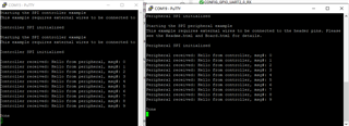
Help confirm that Peripheral was unable to output data when using SPI's controller, Peripheral routines.

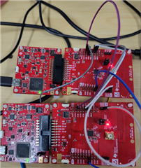
1.The hardware uses two LP-EM-CC2340R5 development boards.

2. SDK: simplelink_lowpower_f3_sdk_7_20_00_29

controller:D:\ti\ccs1240\simplelink_lowpower_f3_sdk_7_20_00_29\examples\rtos\LP_EM_CC2340R5\drivers\spicontroller\freertos\ticlang

Peripheral:D:\ti\ccs1240\simplelink_lowpower_f3_sdk_7_20_00_29\examples\rtos\LP_EM_CC2340R5\drivers\spiperipheral\freertos\ticlang

3. CCS: Code Composer Studio 12.4.0

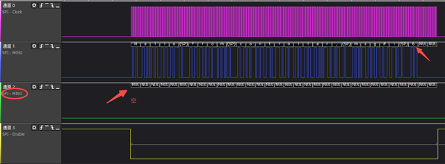
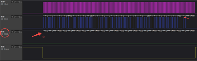
The two adjacent waveforms are as shown, only controller data can be captured and miso data are empty, as shown below: 

Best Regards,

Galaxy

  • Hello Galaxy,

    I just tested the two examples on my end and I was able to receive data (messages) between the devices. You may have missed a wire; I used a total of 7 wires between the devices (all SPI pins, ground, and two from GPIO labeled as SPI_Ready). (My setup was 2x CC2340R5, using the lowpower_7_10_00_35 sdk). 

    Thanks,
    Alex F

  • Hi Alex F,

    Data is correctly inserted: DIO12-, DIO12.

    What is output-to-output? Shouldn't it be an output to an input? DIO13 - DIO13 

    In this case, I can achieve it.

    Best Regards,

    Galaxy

  • Hello Galaxy,

    Are you saying that with the wire connections DIO12 -> DIO13 (on one board), and DIO13 ->DIO12 (on the other board)? My combined wires may of been mixed up slightly. In either case the way in which data is received is the correct way. I will try and re-run the test tomorrow to re-confirm. 

    Thanks,
    Alex F

  • Hi Alex F,

    I've tried that to be correct DIO12->DIO12(from board A to board B),DIO13->DIO13(from board A to board B) is correct and I can  receive data.

    Best and Regards,

    Galaxy

  • Hello Galaxy,

    I just re-ran the previous test and for it to work on my end I needed Board A's DIO 12 to go to Board B's DIO 13, (12A ->13B, 13A - 12B) in order for the data to be transmitted correctly. This makes sense considering the what the PinMux is set to in SysConfig (looking at POCI and PICO), you could try and reverse the POCI/PICO PinMux on one of the boards if needed. 

    Thanks,
    Alex F

  • Hi Alex F,

    1.How to  reverse the POCI/PICO PinMux can give me a shot?  (  the shot of sysconfig)

    2.Why do I set 12A -> 12B, 13A - 13B to communicate properly, what is the deviation? 

    Best  Regards,

    Galaxy

  • Hello Galaxy

    1. Looking at SysConfig we first need to change the "Use Hardware" section inside SPI to "None", this way we can change our POCI/PICO pins. Once the setting is changed to "None" you can set reverse/set pins as needed.

    2. I am not too sure I understand what is stated here. Although I did notice that actually the devices can communicate works both ways (DIO 12/13), however in the configuration I was using earlier (12 A -> 13 B, 13 A -> 12 B) I lost some packets/data, when I switched to (12 A -> 12 B, 13 A -> 13 B) I received all packets clean (and more consistent). To that end you are correct in the configuration you use. 

    For detailed information regarding the SPI please reference the Technical Reference Manual (specifically the SPI section 8.19.2). 

    Thanks,
    Alex F

  • Hi Alex F,

    Thanks for your support!

    I have resolved it.

    Best and Regards,

    Galaxy