This thread has been locked.

If you have a related question, please click the "Ask a related question" button in the top right corner. The newly created question will be automatically linked to this question.

CC2650 : how to make any pin to high impedance ?

Other Parts Discussed in Thread: CC2650EMK, CC2540, CC2650

Hello everyone,

My based device is CC2650emk, I have a question about how to make any pin to high impedance.

I have found the similar question from here,

but his based device is CC2540.

And besides, I found the tristated got a mention in the PIN.h.

however, there was not mode option about it.

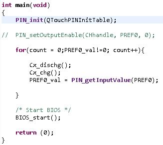
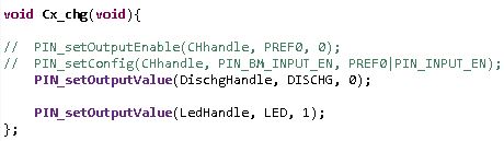
 how can i do, if i want to set any pin to high impedance ?

  • Hello Daiby,

    You can use PIN_GPIO_OUTPUT_DIS.

    Best wishes
  • Hi JXS,

    I have another question.

    If I want to toogle the pin from output to input,

    how can I do that won't affect the input value from the pin.

  • Hello Daiby,

    You can combine both input and output on the same DIO. Here is an pin configuration example:

    PIN_Config PinTable[] = {
     Board_LED0 | PIN_INPUT_EN | PIN_PULLUP | PIN_IRQ_POSEDGE | PIN_GPIO_OUTPUT_EN | PIN_GPIO_LOW | PIN_PUSHPULL | PIN_DRVSTR_MAX,    
     PIN_TERMINATE
    };

  • Hi,

    Can you elaborate your application?
    FYI, you can take a look at our TRM page 880, which has the simplified diagram of IOs
  • Hi Christin Lee,

    The image is the circuit of the Capacitive sensor.

    the DISCHG pin is any pin of  cc2650.

    There are three step of my Capacitive sensor:

    Step1. Precharge the Cs and Cx: DIO_3 is an HIGH ouput and DISCHG is LOW output.

    Step2. Discharging the Cx: DIO_3 is an input and DISCHG is HIGH output.

    Step3.Using Cs to charge Cx: DIO_3 is an input to detect whether the voltage of Cs is close to zero, and DISCHG is LOW output.

    repeat step2 and step3 until the voltage of Cs is close to zero,

    and then, I can get the repeats time.

    However, I always detect the voltage of Cs is close to zero at first repeat.

    I think it because when I configure the DIO_3 to input, the Cs is discharged at the same time.

  • Hi,

    Can you try to use oscilloscope to track the voltage on CH_0?
    I have some questions regarding your design:
    1. When you charge it, are you sue that both CH_0 and CH_P0 reaches 3V?
    2. How long time does step 2 last?

    Can you post your code?
  • Does the "charge" in question1 referre to "precharge" in step1 ?

    The question 2, I just discharge it a moment.