This thread has been locked.

If you have a related question, please click the "Ask a related question" button in the top right corner. The newly created question will be automatically linked to this question.

CC2541 ADC data sampling from an op-amp output and compared with Arduino

Other Parts Discussed in Thread: CC2541, LM358

Hi,

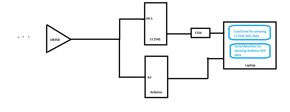
I have CC2541 ADC channel P0.5 connected to an LM358 opamp output.

The ADC sampling rate is 1 sample/sec, Vref is AVDD, resolution 10 bit, Vcc is 3V.
The opamp generates a constant voltage of approximately 12mV. I am using HAL adc functions to read the ADC data by editing SimpleBLEPeripheral. 

I am sending the ADC data to my PC using CC2541's UART and see the data using CoolTerm.

For 12mV opamp output, I am supposed to get an ADC data of (1023/3)*.012 = 4.
However, I see that the ADC data is varying from 0 to 6. (which is approximately from 0v to 17mV)

Interestingly, I have also sampled the same op-amp output using an Arduino with similar ADC configuration. Here, the ADC data did not vary too much.
It varied from 3 to 4 (which is approximately from 8mV to 12mV).

Is there a way I can reduce the ADC data variation in CC2541?

I tried to solve the problem by connecting a 1uF decoupling capacitor from P0.5 to GND, however, I do not see any improvement.

Any suggestions?


Thanks.

Tareq

  • Hi Tareq,

    Can you post screenshots of your oscilloscope showing the input to the ADC? Can you share your changes to enable the ADC?
  • Hi, I have the circuit connected as shown above. Both CC2541 and Arduino are getting the SAME input analog voltage at the ADC input. They both have equal ADC reference voltage. However, when I look at the data in my laptop, I see that the CC2541 ADC data is changing a lot compared with Arduino. 

    Below is an example:

    CC2541 ADC data Arduino ADC data
    2 4
    3 3
    5 3
    2 3
    3 3
    3 3
    3 3
    3 3
    1 3
    2 3
    4 3
    3 3
    3 3
    4 4
    3 4
    3 4
    3 4
    3 4
    3 4
    2 4

    My question is why CC2541 data is varying from 1 to 5 whereas the Arduino data is more stable (varying on;y from 3 to 4)? How can I stable the CC2541 ADC data?

    Do you still need to see Oscilloscope trace of the input signal? If yes, I can provide it in the next reply. Note that, both MCUs are getting the same signal and I was expecting the same data from both the MCUs.

    From SimpleBLEPeripheral program, the code samples ADC data after each 1 second (using SBP_PERIODIC_EVT). It calls the function as below:

    adc_val = HalAdcRead (HAL_ADC_CHANNEL_5, HAL_ADC_RESOLUTION_10) ;

    In hal_adc.c, I have modified the HalAdcRead() as below. Changes are shown in Bold:


    uint16 HalAdcRead (uint8 channel, uint8 resolution)

    {

      int16  reading = 0;

    #if (HAL_ADC == TRUE)

      uint8   resbits;

      //uint8  adcChannel = 1; //Tareq

      /*

       * If Analog input channel is AIN0..AIN7, make sure corresponing P0 I/O pin is enabled.  The code

       * does NOT disable the pin at the end of this function.  I think it is better to leave the pin

       * enabled because the results will be more accurate.  Because of the inherent capacitance on the

       * pin, it takes time for the voltage on the pin to charge up to its steady-state level.  If

       * HalAdcRead() has to turn on the pin for every conversion, the results may show a lower voltage

       * than actuality because the pin did not have time to fully charge.

       */

    // if (channel <= HAL_ADC_CHANNEL_7)

    //  {

    //    for (i=0; i < channel; i++)

    //    {

    //      adcChannel <<= 1;

    //    }

    //

    //    /* Enable channel */

    //    ADCCFG |= adcChannel;

    //  }


      APCFG |= (BV(channel)) ; //Tareq


      /* Convert resolution to decimation rate */

      switch (resolution)

      {

        case HAL_ADC_RESOLUTION_8:

          resbits = HAL_ADC_DEC_064;

          break;

        case HAL_ADC_RESOLUTION_10:

          resbits = HAL_ADC_DEC_128;

          break;

        case HAL_ADC_RESOLUTION_12:

          resbits = HAL_ADC_DEC_256;

          break;

        case HAL_ADC_RESOLUTION_14:

        default:

          resbits = HAL_ADC_DEC_512;

          break;

      }


      /* writing to this register starts the extra conversion */

      ADCCON3 = channel | resbits | adcRef;

      /* Wait for the conversion to be done */

      while (!(ADCCON1 & HAL_ADC_EOC));

      /* Disable channel after done conversion */

      // We do not want to disable the channels of APCFG. they are required for AC.

      // disabling this creats high voltage problem on the ADC pins. //Tareq

      //ADCCFG &= (adcChannel ^ 0xFF);


      /* Read the result */

      reading = (int16) (ADCL);

      reading |= (int16) (ADCH << 8);


      /* Treat small negative as 0 */

      if (reading < 0)

        reading = 0;

      switch (resolution)

      {

        case HAL_ADC_RESOLUTION_8:

          reading >>= 8;

          break;

        case HAL_ADC_RESOLUTION_10:


          //reading >>= 6; 

          reading >>= 5; //Tareq


          //ADCH: D13  D12 D11 D10 D9  D8  D7  D6 

          //ADCL: D5   D4  D3  D2  D1  D0  0   0


          // D13 is sign bit, it is always zero.

          // When righshift 5 bits, we get

          // 0  D12  D11  D10  D9  D8  D7  D6  D5  D4  D3

          // which is 10 bit data.


          break;

        case HAL_ADC_RESOLUTION_12:

          reading >>= 4;

          break;

        case HAL_ADC_RESOLUTION_14:

        default:

          reading >>= 2;


        break;

      }

    #else

      // unused arguments

      (void) channel;

      (void) resolution;

    #endif


      return ((uint16)reading);

    }

  • Hi Khan,

      The impedance of Arduino and cc2541 will affect each other if you connect them this way and they share the same output.

    Its better to measure them separately.