This thread has been locked.

If you have a related question, please click the "Ask a related question" button in the top right corner. The newly created question will be automatically linked to this question.

CC2640: Voltage on VDDR / DCOUPL down to zero

Part Number: CC2640
Other Parts Discussed in Thread: CC2650

Good morning,

We are using the CC2640 for our project since a year now and we have sometime an issue I can't find the origin.

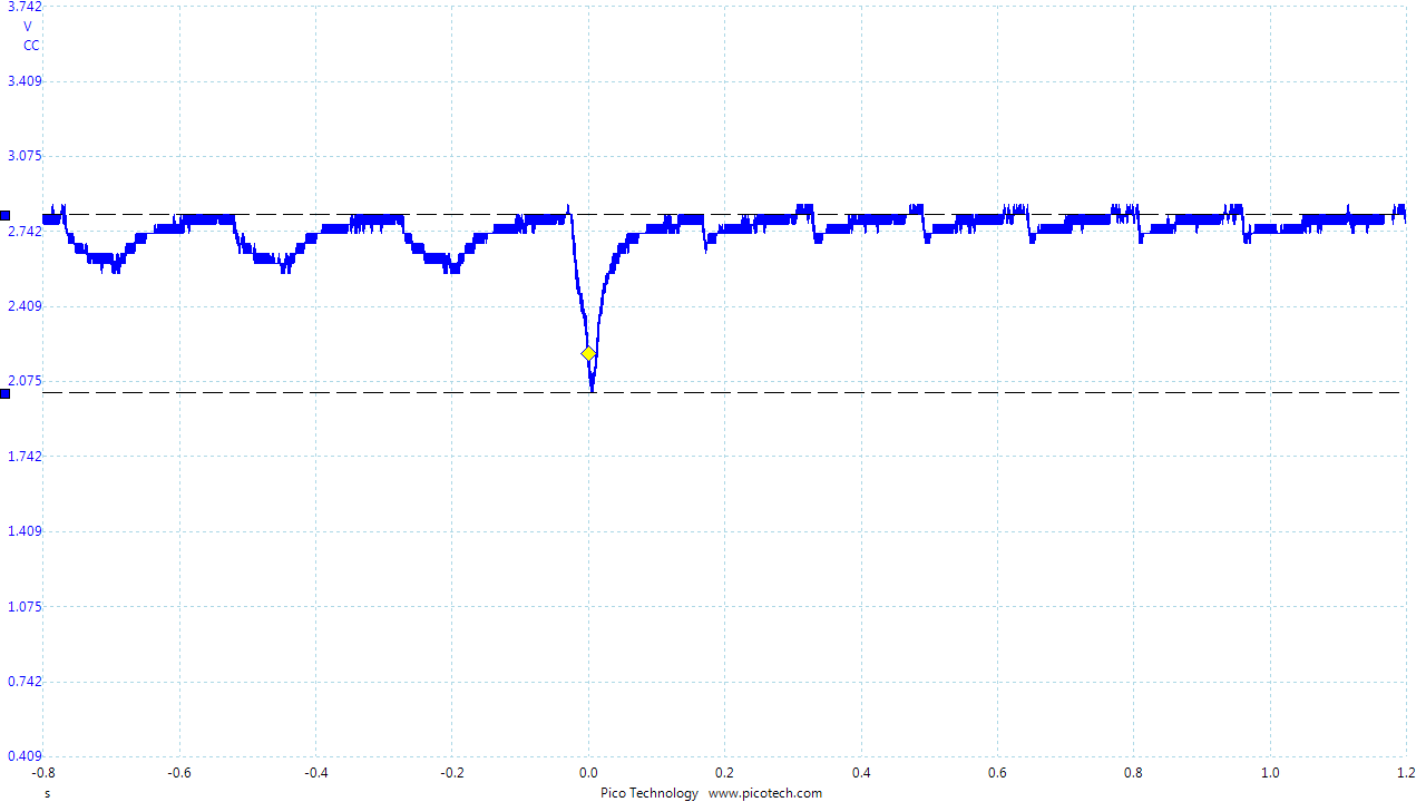
After a few days, the Advertising seems to be disabled, and voltage on VDDR pin and DCOUP pin are down to zero. As far as I know, the only way to get to this state is by decreasing the global voltage power to ~1.7V while the system is working. We use a CR1616 battery and 2x47uF tantalum capacitors on the VDDS pins, everything else is like on the reference design.

Is there any other possibility (like a software issue) that can lead to this state ? Is it possible to prevent the system or trigger this voltage ?

Thanks in advance

  • Hi,

    What you are seeing is documented in our datasheet. You can find all the information on our datasheet page 35, section Power Management, note 2.
  • Hi Christin,

    Thanks a lot for your response, it helped me a lot.

    I have discovered that when I stop an existing connection, depending on what i'm doing in the software, there is a huge amount of current used by the application. With 3 times 47uF Tantalum capacitors and a CR1616 (20% used maybe), i catched a 800mV dropout, going close to 2V.

    On the following picture, I was connected with 200ms interval and i quit the ble connection. Before the voltage drop, a motor is driven by the sensor controller between the interval connections. After the voltage drop we can see the Advertising current consumption.

    I think that the problem appears when I start a new task (used to control a motor with the sensor controller while the system is in standby mode). 

  • I'm trying to catch again this voltage drop but for now it is unsuccessful... I will add a Task_sleep(200) after each connection event before starting the new task for the sensor controller.
  • I have catched a new voltage drop on my circuit, and this one makes the system crash. The peripheral was only connected, no motor control, and after two minutes without reading/writing, I close the connection. The voltage occurs a that time, going to 1.81V : 

    I spend one afternoon chasing this current consumption, and I been able to see 5-10 of them but only every 20 tries. What could cause so much current consumption ?

    // RF output configuration
    while(HCI_EXT_SetTxPowerCmd(HCI_EXT_TX_POWER_0_DBM) != SUCCESS)
    	Task_sleep(10);
    while(HCI_EXT_SetMaxDtmTxPowerCmd(HCI_EXT_TX_POWER_0_DBM) != SUCCESS)
    	Task_sleep(10);
    while(HCI_EXT_SetFastTxResponseTimeCmd(HCI_EXT_DISABLE_FAST_TX_RESP_TIME) != SUCCESS)
    	Task_sleep(10);
    
    // End of connection 
    
    if (events & PERI_CONNECTION_CLK_EVT )		// Stop connection (after ~2minutes)
    {
    	events &= ~PERI_CONNECTION_CLK_EVT;	// Reset event
    	Util_stopClock(&Clock_EndConnection);	// Stop ConnectionClock
    
    	GAPRole_TerminateConnection();		// End connection
    }

    Any help is welcome

  • Hi,

    I am not sure what's causing this but I would recommend you to add an IO toggle in the code to identify at which point of the code the drop happened.
  • Hi,

    An IO toggle ? Like a breakpoint ? I can't have this error with CCS connected to the PCB.
  • An IO toggle is not a break point.

    What I meant is for example modifying your code to the following :

    while(HCI_EXT_SetTxPowerCmd(HCI_EXT_TX_POWER_0_DBM) != SUCCESS)
    --> ioToggleOnce
    while(HCI_EXT_SetMaxDtmTxPowerCmd(HCI_EXT_TX_POWER_0_DBM) != SUCCESS)
    --> ioToggleTwice
    while(HCI_EXT_SetFastTxResponseTimeCmd(HCI_EXT_DISABLE_FAST_TX_RESP_TIME) != SUCCESS)
    --> ioToggleThreeTimes

    ... etc

    Use Oscilloscope to track the voltage level and IO pin to see how the voltage drop mapped to the IOtoggle.
  • I let my system working all the week-end, and put a trigger with a current monitoring to see if anything happen :

    Between two advertising events (30 seconds), the motor started and, suddenly, 12mA of current were used. I don't think that the CC2640 could use that amount of current event is something is wrong in my code ? It has to be an external element (as the motor)  ? The pike is 35ms long, and a motor step is 10ms or less, so for now I'm not sure.. as these pikes are hard to reproduce.

    A closer look :

  • Is it possible to just run CC2640 without the motor? Then it will be easier to check if the extra current comes from there.
    How did you implement the code for running motor?
  • My application is divided in two tasks : The first one is managing BLE events and profiles read/writes, the second one is used to manage the sensor controller. The second task is in standby mode while the sensor controller is working, and waked up every 10 ms when the sensor controller finished it's task. Then it start again until the sensor controller did all the steps.

    In the first task, between the Advertising events, a clock is started every 200ms, creating a "starting_steps_events" :

    if (events & PERI_END_ADV_START_EVT)
    {
    	events &= ~PERI_END_ADV_START_EVT;	// Reset event
    	Util_stopClock(&Clock_StartSteps);	// Stop clk
    
    	// Start steps
    	if(gapProfileState == GAPROLE_WAITING  && Sensor_state == SENSOR_PAUSE)	// Not working and waiting gaprole state
    	{
    		const uint16_t Steps = PERIODIC_SENSOR_TIME / STEP_TIME ;			// Max steps for 200ms
    		volatile uint16_t Scheduled_start = 0;
    		Peri_fw21_StartStop_Sensor(Steps, 0);								// Start Sensor Controller
    
    		// Schedule next start
    		if(Flow_adapt_cnt_u16_gl < Flow_adapt_cnt_max_u16_gl)
    			Scheduled_start = PERIODIC_SENSOR_TIME * (Flow_adapt_cnt_max_u16_gl - Flow_adapt_cnt_u16_gl) ;
    		else
    			Scheduled_start = PERIODIC_SENSOR_TIME * Flow_adapt_cnt_max_u16_gl ;
    
    		// Restart if possible
    		Waiting_adv_time_counter_u16_gl += Scheduled_start;
    		if( Waiting_adv_time_counter_u16_gl < (DEFAULT_ADVERTISING_TIMEOFF - PERIODIC_SENSOR_MARGIN) )
    		{
    			Util_restartClock(&Clock_StartSteps, (uint32_t) Scheduled_start );	// Start clock for advertising management
    			Flow_adapt_cnt_u16_gl = Flow_adapt_cnt_max_u16_gl;
    		}
    	}
    	else if (Sensor_state == SENSOR_WORKING)
    	{
    		// Send error
    		volatile uint8_t status = 0;
    		status = peri_fw21_CheckOvertimeError(gapProfileState);
    		Peri_fw21_SensorStopRequest(status);
    	}
    }

    The StartStop_Sensor function will calculate how much steps I have to do and then create a Task to manage the sensor controller. This Task start the sensor controller every 10ms for a new step.

    static void Peri_fw21_Sensor_taskFxn(UArg a0, UArg a1)
    {
    	SensorController_init();	// Initialize application
    
    	// Reset structure cfg and state
    	scifResetTaskStructs(BV(SCIF_ASSERVISSEMENT_TASK_ID),BV(SCIF_STRUCT_CFG));
    	scifResetTaskStructs(BV(SCIF_ASSERVISSEMENT_TASK_ID),BV(SCIF_STRUCT_STATE));
    
    	scifTaskData.asservissement.cfg.TotalSteps = Sensor_TotalSteps ; 	// Set total steps
    	scifTaskData.asservissement.cfg.period = SENSOR_PERIOD ;			// Set Period
    	scifTaskData.asservissement.cfg.rotation = 1 ;					// Start always same way
    	scifTaskData.asservissement.cfg.CurrentSteps = 0;	// reset steps
    	scifTaskData.asservissement.cfg.MissedSteps = 0;	// reset missed steps
    	scifTaskData.asservissement.cfg.Periodstep = 0;	// reset the period of steps
    	scifTaskData.asservissement.state.HallDetected = 0;	// Reset Hall Detected flag
    	scifTaskData.asservissement.state.StepsFromHall = 0;	// Reset Steps from last Hall detection
    
    	if(SCIF_SUCCESS == SensorController_start_once())
    	{
    		// Wait semaphore
    		Semaphore_pend(Semaphore_handle(&semScTaskAlert), BIOS_WAIT_FOREVER);
    		scifClearAlertIntSource();
    
    		// Stop sensor controller
    		scifAckAlertEvents();
    		while(SensorController_stop() != SCIF_SUCCESS) { Task_sleep(100); }
    	}
    
    	*Sensor_state = SENSOR_PAUSE;	// Inform that sensor did it's job
    }
    /* Start one time init-execute-terminate session */
    SCIF_RESULT_T SensorController_start_once()
    {
    	scifStartRtcTicksNow(0x000000024);	// Start ticks on RTC Ch2, bit 15:0 -> 1/65536 of seconds
    
    	// Open the AUX I/O latches, which have undefined value after power-up. AUX_AIODIO will by default
    	// drive '0' on all I/O pins, so AUX_AIODIO must be configured before IOC
    	HWREG(AUX_WUC_BASE + AUX_WUC_O_AUXIOLATCH) = AUX_WUC_AUXIOLATCH_EN_TRANSP;
    
    	scifTaskResourceInit();	// Start I/O
    
    	return scifCtrlTasksNbl(BV(SCIF_ASSERVISSEMENT_TASK_ID), 0x01);	// Init and execute and terminate
    }

    So basically, every 200ms a task is created to manage the sensor controller. It works well every time and I had to wait more than a day to trigger this current pike. It happened when the Start_steps event occurred and used 25ms to reach the 12mA. Then is fall down and my timing is respected again. But these 25ms are not used by my application, something is wrong because it creates a shift in my global timing table. 

  • The 25ms could be due to the hysteresis of the battery charging/discharging. I don't think it's due to the actual task process time. You will have to find out why there is a 12mA usage(peak) all of the sudden on your own application. Also make sure the internal resistance of the battery you are using is not too high. (For the internal resistance of the battery, you should be able to find it in the datasheet)

    For normal advertising/connection and current consumption of a CC2640/CC2650 can be found here( www.ti.com/.../swra478 ), but this is the number without any peripheral in use. I am guess what you are seeing is the peripheral is on while the radio is also running, you can try to avoid this by making sure that you run the sensor controller execution code at the end of the advertising.
  • Actually, there was no connection/advertising during the current peak. It could come from :
    - System coming out of standby
    - Problem while creating a new task
    - I/O issue during motor drive, but the internal resistance of the self is about 900 ohms, so with a 3V battery I have about 1mA max
    - Discharge of of the self voltage through an equivalent 250 ohm resistance (that would give 12mA).
    - Something else, caused by the battery ?

    I'm using a CR1616 lithium battery, but not internal resistance is not specified. The firm said that i could change quite a lot between the batteries. It should be around 80-100 ohms following energizer datasheet. For the current application, they are not powerful enough, but this is the smallest batteries we found that could drive our application for several weeks.

    To help the CR1616, we use three tantalum capacitors of 47uF each.
  • Can you try to just run sensor controller code together with the running motor? So we can separate the current from BLE stack and the sensor controller.

    And see if you can find if there is a pattern for how frequent this could happen, probably also try to increase the task interval to let the battery have more time to recover from the previous drop.
  • I tried something else yesterday : Instead of using a battery, i used a power supply. In the same time I changed the software to pull down both outputs driving the motor before each start. 

    It turned all night, nothing on the screen.

    This morning I used my smartphone to stop the motor, and start a new test with more steps. I found something really interesting when I stopped the BLE. The first picture is the disconnection when everything goes right : It takes around 20ms and I choose to let some time between the end of connection, and start of advertising (to let the battery recover between this two events).

    Maximum current 7.4mA 


    Here is the picture of the current when I stopped the BLE this morning (configuration, software, power supply and everything is the same with the previous picture) : 

    The maximum current used is 12.5mA and the time used for the two events is 43ms. In previous tests, we saw a current peak of 12mA for 25ms at the start of my sensor controller task. Here the sensor controller task is blocked, waiting for Advertising to end before using the motor again. 

    This peaks of current have been detected when : 

    - Disconnection of the BLE and start of Advertising (several times)

    - Starting the motor and sensor controller while Gaprole was waiting. 

    If the sensor controller, the task creation or the motor control was the problem, I should have seen it during the night. I started the system again with the motor at full speed. No BLE connection, just waiting if there is a peak in this configuration. But it seems that my CC2640 has a weird behavior...

  • By looking at the previous test, i saw something else : 

    When the current peak has been detected while running the sensor controller, it can not come from the motor. Because the timing has been shifted for the current peak ! And same for the previous one during disconnection : 

    Each start of the sensor controller has to occur every 200ms. An event generated by a clock is managing this. But the from the start of the current peak and the maximal value of the current peak, there is 25ms where the sensor controller is not working. Coming out from standby and gaprole waiting situation, this peak shifted everything. 

  • The lock up issue only happens in standby. All the BLE activity does not happen in standby.
    If the voltage drop is too big in active, then device will just restart.

    The only recommendation I can give you is monitor your current consumption when you are in standby and then if the current consumption gets too high, you need to disable power_saving from the SW.
  • It should be the case, but how a system staying in standby could create such a peak ? Could it come from the DC/DC converter or RAM retention ?

    Could an hardware issue have an impact on the RTOS ? Because this current peak increased the time for BLE disconnection, and the current is not going down before increasing to 12mA, the CC2640 seems to be in active mode. 

  • CC26xx does not create such a peak, but any external components that source current from CC26xx could make a drop when device is in standby.
  • If the peak is coming from an external component, the disconnection event should take the same amount of time. Here it takes 25ms more because of the peak. This I can't understand.
  • You will need to have a sniffer to see what's actually happening over the air to be sure what's going on for the previous two plot. Or again, you need to implement IO toggling to identify which part of the code is running to get a better understanding of what's going on.
  • Hi,

    I still haven't fixed the problem, but today I will build a small trigger system in order to stop the CC2640 with a pin interrupt and look inside the RTOS object viewer. What happened in the last days : 

    - I tried to change some configuration parameters, like optimization or stack size. Nothing changed.

    - I take a look on the VDDR voltage, to see if it drops before the current peak, but it doesn't. They fall at the same time.

    - I simplified my software before creating the Sensor task, and the peaks where easier to catch, happening every 2 minutes instead of 6 hours.

    - I decided then, instead of creating the Sensor task, to make it sleep and wake the task with a semaphore.

    - Again, the peak came every 6-10 hours. So the problem is not coming from creating or waking up the task. It is something else related to the CC2640 or the RTOS.

    - I blink a LED when the system wakes up the Sensor task, and the LED blink when the peak is at its maximum value. 

    So for now, I can conclude that as the global timing of my application is shifted to let this peak occur, that it comes before using the motor or I/O. Something is happening when the system wakes-up. I'm currently running the system with the LED blinking right after the IcallWait function. We will see if again the LED is blinking at the top of the current peak.

    About the other problem :

    I read the btsnoop_hci file in the Android system connected to see what happened. It seems that the Android ask for disconnection, received notifications, and then accept disconnection. It could come from my Android software, maybe i should disable notification before disconnection.

  • I found the problem. It comes from a write in the flash memory with a osal_snv_write. 

    #include <stdio.h>
    #include <stdlib.h>
    #include <string.h>
    
    #define TWO_BYTE    2
    #define FOUR_BYTE   4
    #define SEVEN_BYTE  7
    
    #define HI_UINT16(a) (((a) >> 8) & 0xFF)
    #define LO_UINT16(a) ((a) & 0xFF)
    
    #define STATE_MISSED_STEPS_CURRENT	9	    // Number of steps missed in current dose, Profile value
    #define LOG_CODE_MISSED_CUR		    4       // Log code number, for missed steps
    #define LAST_LOG_VALUE			    0x88    // Flash address for last log value
    
    typedef unsigned char  uint8_t;
    typedef unsigned short uint16_t;
    typedef unsigned int   uint32_t;
    
    typedef enum
    {
    	PROFILE_ACTION = 0, PROFILE_STATE       // Type of profiles, action or state
    
    } Profile_type ;
    
    void UpdateStepsProfiles(const uint32_t Current, const uint16_t Missed, const uint8_t flag);
    void WriteInProfile(const uint8_t Parameter, const uint8_t Size, void *ptr_param, const Profile_type Profile, const uint8_t Notification_flag);
    void WriteLog(void *ptr_param);
    
    int main()
    {
        // System wakes up from standby, read values from scifTaskData
    
        uint32_t Current_steps_u32 = 2500;      // Motor make some steps
        uint16_t Missed_steps_u16 = 16;         // 16 steps have been missed
        uint8_t flag = 0;                       // Notification flag
    
        if(Missed_steps_u16)    // All steps missed are written in a log profile
            flag = 1;           // Set the flag
    
        UpdateStepsProfiles(Current_steps_u32, Missed_steps_u16, flag); // Update profiles and log
    
        return 0;
    }
    
    void UpdateStepsProfiles(const uint32_t Current, const uint16_t Missed, const uint8_t flag)
    {
        uint8_t Missed_steps[TWO_BYTE] = {0};
    
        if(flag)
    	{
    		Missed_steps[0] = (uint8_t) HI_UINT16( ((uint16_t)Missed)) ; //(( Missed >> 8 ) & 0xFF );
    		Missed_steps[1] = (uint8_t) LO_UINT16( ((uint16_t)Missed)) ;
    		WriteInProfile(STATE_MISSED_STEPS_CURRENT, TWO_BYTE, Missed_steps, PROFILE_STATE, 1);
    	}
    }
    void WriteInProfile(const uint8_t Parameter, const uint8_t Size, void *ptr_param, const Profile_type Profile, const uint8_t Notification_flag)
    {
        uint8_t Time[FOUR_BYTE] = {0} ;	// Total time since start (array)
    
        // .. function to get time value from profile
    
       	switch(Parameter)
    	{
            case STATE_MISSED_STEPS_CURRENT:            // If steps have been missed
    		{
    			uint8_t missed[TWO_BYTE] = {0};
    			memcpy(missed, ptr_param, TWO_BYTE );   // Copy the ptr_param
    
    			uint8_t Log_info[SEVEN_BYTE] = {Time[0], Time[1], Time[2], Time[3], LOG_CODE_MISSED_CUR, missed[0], missed[1]};
    			WriteLog(Log_info);                     // Write in log profile
    		}
    		break;
    	}
    }
    void WriteLog(void *ptr_param)
    {
        volatile uint8_t log_index = 0;	// Index to write in log profile
    
        // ... move logs in profiles to insert the last one
    
        log_index = 0;
    
    	// ... write in profile the last log event with log_index = 0
    
        // Write in OSAL to save the last event if a reset occurs
    	osal_snv_write(LAST_LOG_VALUE, SEVEN_BYTE, ptr_param);      // 12mA current peak is coming from this line
    }
    

  • Hi,

    Glad you found where the large current comes from. If you comment out that line, will the problem disappear? When did you call the osal_snv_write(the end of adv? connection?)?
  • Yes, by removing the line the problem disappear. This write is coming every 200ms (clock based) between Advertising events (they occur every 30 seconds for 1 second) and right after every connection event if the connection interval is 200ms. The sensor controller start the motor after this write and stop before the next event (triggered by the clock or a connection event).
  • I'm trying to make it work by changing the address (LAST_LOG_VALUE) from 0x88 to 0x80 but the current peak are still here, I had also other calls to osal_snv_write in the software, I removed them but there is no change.  

    I changed the line like this, as in the official example, but there is no change.

    // Address
    #define LAST_LOG_VALUE 0x80
    #define LAST_LOG_VALUE 0x88 // Nothing changed
    
    // Line changes
    osal_snv_write(LAST_LOG_VALUE, SEVEN_BYTE, ptr_param);
    osal_snv_write(LAST_LOG_VALUE, SEVEN_BYTE, (uint8 *)ptr_param);  // Nothing changed

  • Changing the ItemID is not going to affect the current consumption. Why do you need to write to the flash that often? The battery you are using is really sensitive to current spikes(flash write operation certainly will cause higher current ). You can save the data in the RAM and use it later if you don't intend to have battery replace in between.
  • Well if the battery fail, it could be interesting to read the last log value or how much time the system worked. How many bytes can I write in a single address (like 0x80) 4 bytes or 1 byte ?
  • The reason it failed is because of the flash write, when you have such a weak battery, you should again try to avoid doing so. If all you want is debug information, why not just use UART logging?
  • The current peaks are visible even with a power supply. How is it possible for the CC2640 to use some much energy ? Is there a way to avoid it ? If I remove the power supply and put it back, how can i read previous values without flash read/writes ?

    Thanks in advance