This thread has been locked.

If you have a related question, please click the "Ask a related question" button in the top right corner. The newly created question will be automatically linked to this question.

CC2640R2F: RF front end design questions

Part Number: CC2640R2F

Reference to the diagram below (Figure 7-1, page 41 of CC2640R2F datasheet)

1. For differential operation, external bias, it requires a 6.2 to 6.8nH inductor (in red). Can you describe the function of this inductor, and how it works, and why it is necessary during external bias mode?

2. For single end operation, external bias, it requires a 15nH inductor (in red). Can you describe the function of this inductor, and how it works, and why it is necessary during external bias mode?

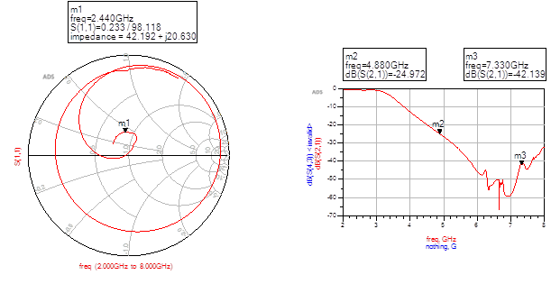
3. For differential operation, based on recommended circuit below (for both internal & external bias), what is the estimated insertion loss?

  • Hi Eddie,

    1./2. The inductors are used to connect the DC bias voltage to the active RF pin(s).
    3. The numbers in the datasheet are measured at the end of the balun and RF match.

    Regards,
    Fredrik
  • Hi Fredrik,

    This is Zhi Wei. For your answer in (3), you mentioned that the numbers in the datasheet are measured at the end of the balun and RF matching circuit. Are you referring to the TX output power measurement? FYI, I am using the TI reference front end circuit for my circuit design, but I measured a relatively low TX output power from the TI chipset. Do you have the insertion loss information on the balun and RF matching circuit of the reference design as I couldn't find them in the datasheet?

    Thanks.

    Best Regards,
    Zhi Wei
  • Hi Zhi Wei,

    All datasheet numbers, including output power, are measured at the output of the RF circuitry. There is no insertion loss that must be subtracted from the datasheet values.

    If you are getting low output power you most likely have a HW problem in your design, or incorrect RF configuration in SW.

    Refer to the HW section of the BLE wiki for details: www.ti.com/ble-wiki

    Cheers,
    Fredrik
  • Hi Fredrik,

    Thanks for your reply. I have another quick question on the RF front end design.

    For the layout, may I know whether both traces connected to the differential input/ output pins of CC2640R2F (RF_N and RF_P) has to be 50 ohms individually? From the reference design layout, I do notice that the trace width reduces as it moves from the balun stage to the differential input/ output pins of the TI chipset (see the white box). Please advise. Thanks.

    Best Regards,

    Zhi Wei

  • Hi Zhi,

    The impedance of the differential trace is not defined. The trace length is anyway so short that it does not matter.

    Regards,
    Fredrik
  • Hi Fredrik,

    Thanks for your reply.

    I do notice that the simulated optimal load impedance of CC26XX (differential internal bias) is 42.192 + j 20.630 (from the TI wiki page).

    processors.wiki.ti.com/.../CC26xx_Optimal_Load_Impedance

    Is this value the same as the output differential impedance of the RF_N and RF_P of the CC26XX chipset? In another word, when I design a balun for the TI chipset, do I need to ensure that the input differential impedance of my balun is conjugated matched to this value?

    For the traces which connect the balun to the differential output of the chipset (RF_N and RF_P), does each of the trace has to de designed so that it has a characteristic impedance of (differential impedance / 2) for optimal power transfer?  

    Please advise. Thanks.

    Best Regards,

    Zhi Wei

  • Hi Zhi Wei,

    These are simulations of the differential input into the differential end of the balun in our reference design. As is explained in the wiki article, you should not design your own balun, but use on of the reference designs.

    As I mentioned earlier in this thread, the dimensions of the differential trace is not important due to the short length.

    Cheers,
    Fredrik