Part Number: CC2642R
Hi,
Here are some steps to enable periodic advertising on CC2642R, CC2652R or CC2652R7.
This guide assumes you are using the simple_peripheral example for the device selected. This guide has been tested on SDK 7.10.00.98.
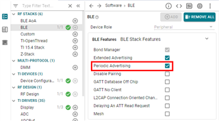
1- Enable support for Periodic Advertising in SysConfig
2- Create a new advertising set in SysConfig
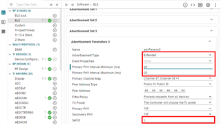
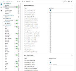
3- Setup the advertising data for the newly created advertisement set
4- Save and close SysConfig
5- (Optional) Disable the other advertisements set by commenting out the "GapAdv_enable" commands found
6- Add the global data needed
 // Create non connectable & non scannable advertising
#define GAPADV_PARAMS_AE_NC_NS {                                           \
  .eventProps = 0,                                                         \
  .primIntMin = 160,                                                       \
  .primIntMax = 160,                                                       \
  .primChanMap = GAP_ADV_CHAN_ALL,                                         \
  .peerAddrType = PEER_ADDRTYPE_PUBLIC_OR_PUBLIC_ID,                       \
  .peerAddr = { 0xaa, 0xaa, 0xaa, 0xaa, 0xaa, 0xaa },                      \
  .filterPolicy = GAP_ADV_WL_POLICY_ANY_REQ,                               \
  .txPower = GAP_ADV_TX_POWER_NO_PREFERENCE,                               \
  .primPhy = GAP_ADV_PRIM_PHY_1_MBPS,                                      \
  .secPhy = GAP_ADV_SEC_PHY_1_MBPS,                                        \
  .sid = 1                                                                 \
}

static uint8 advHandleNCNS;      // Non-Connactable & Non-Scannable

// Periodic Advertising Data

static uint8_t periodicData[] =

{
  'P',
  'e',
  'r',
  'i',
  'o',
  'd',
  'i',
  'c',
  'A',
  'd',
  'v'
};
7- Add the following code at the end of the handling of the GAP_DEVICE_INIT_DONE_EVENT event in SimplePeripheral_processGapMessage()
        // Create Advertisement set #3 and assign handle
        GapAdv_params_t advParamNonConn = GAPADV_PARAMS_AE_NC_NS;

        status = GapAdv_create(&SimplePeripheral_advCallback, &advParamNonConn,
                                             &advHandleNCNS);

        // Load advertising data for set #3 that is statically allocated by the app
        status = GapAdv_loadByHandle(advHandleNCNS, GAP_ADV_DATA_TYPE_ADV,
                                     sizeof(advData3), advData3);


        // Set event mask for set #3
        status = GapAdv_setEventMask(advHandleNCNS,
                                     GAP_ADV_EVT_MASK_START_AFTER_ENABLE |
                                     GAP_ADV_EVT_MASK_END_AFTER_DISABLE |
                                     GAP_ADV_EVT_MASK_SET_TERMINATED);


        // Enable non connectable & non scannable advertising for set #3
        // This is a must in order to enable periodic advertisement
        status = GapAdv_enable(advHandleNCNS, GAP_ADV_ENABLE_OPTIONS_USE_MAX , 0);


        // Set Periodic Advertising parameters
        GapAdv_periodicAdvParams_t perParams = {240, 240, 0x40};
        status = GapAdv_SetPeriodicAdvParams(advHandleNCNS, &perParams);
8- Add the handling for GAP_ADV_SET_PERIODIC_ADV_PARAMS_EVENT and GAP_ADV_SET_PERIODIC_ADV_DATA_EVENT events within SimplePeripheral_processGapMessage()
    case GAP_ADV_SET_PERIODIC_ADV_PARAMS_EVENT:
    {
        uint8_t status;
        GapAdv_periodicAdvData_t periodicDataParams = {0x03, sizeof(periodicData), periodicData};
        status = GapAdv_SetPeriodicAdvData(advHandleNCNS, &periodicDataParams);
    }
    break;

    case GAP_ADV_SET_PERIODIC_ADV_DATA_EVENT:
    {
        uint8_t status;
        status = GapAdv_SetPeriodicAdvEnable(1, advHandleNCNS);
    }
    break;
9- (Optional) Enable the RF Observables as described in the Debugging Guide (really useful when not having a Bluetooth Sniffer).
In main.c add the following include: "#include <driverlib/ioc.h>"
Then add the following code right after Board_initGeneral()
  // Map LNA enable pin RFC_GPO0 to DIO6
  IOCPortConfigureSet(IOID_6, IOC_PORT_RFC_GPO0,
                      IOC_IOMODE_NORMAL);
  // Map Tx start pin RFC_GPO3 to DIO7
  IOCPortConfigureSet(IOID_7, IOC_PORT_RFC_GPO3,
                      IOC_IOMODE_NORMAL);
10- Build the code and flash the device
Hexfile for CC26X2R1 LaunchPad enabling periodic advertising: /cfs-file/__key/communityserver-components-multipleuploadfilemanager/d35fa551_2D00_8bfa_2D00_42ea_2D00_8c7f_2D00_ea501b1a1ce7-370266-complete/simple_5F00_peripheral_5F00_CC26X2R1_5F00_LAUNCHXL_5F00_tirtos7_5F00_ticlang.hex
Hexfile for CC2652R7 LaunchPad enabling periodic advertising: /cfs-file/__key/communityserver-discussions-components-files/538/simple_5F00_peripheral_5F00_LP_5F00_CC2652R7_5F00_tirtos7_5F00_ticlang.hex
Please also check Synchronizing with a periodic advertising train - https://e2e.ti.com/support/wireless-connectivity/bluetooth-group/bluetooth/f/bluetooth-forum/1295835/faq-cc2642r-synchronizing-with-a-periodic-advertising-train-cc2642r-cc2652r7
I hope this will help,
Best regards,
Part Number: ZIGBEE-POWER-CALC
TI is pleased to announce a new TI Arm Clang Compiler Tools release 3.2.0.LTS which includes the following new features.
New features:
Part Number: CC2340R5
Hi,
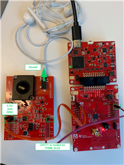
Here is a step by step guide showing how to use the PWM example to produce a siren-like sound.
The example is based on F3 SDK 7.20.00.29.
A BOOSTXL-AUDIO is used to turn the PWM into sound (but other hardware could also be considered).
1- Apply the PWM patch by copy pasting the content of this zip file into the SDK installation (only required for SDK 7.20.00.29) /cfs-file/__key/communityserver-discussions-components-files/538/7532.pwm_5F00_patch.zip
2- If not already done, open CCS, create a workspace and configure it to use FreeRTOS.
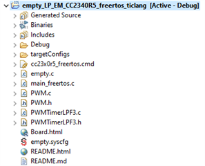
3- Import the empty project from the SDK. For sanity, build the project once.
4- Copy in the project the files PWM.c, PWM.h, PWMTimerLPF3.c, PWMTimerLPF3.h. These files are in the folder <SDK>\source\ti\drivers.
5- Configure the PWM driver in SysConfig. Note that we enable the PWMsignal and its complementary channel (even if it not used here).
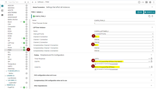
Once done, save, and close SysConfig.
6- Modify the code to use the PWM driver. I mainly used the code snippets provided in PWM.h.
All the changes are made in the empty.c file (the content should be used to replace the content of empty.c)
/*
 *  ======== empty.c ========
 */

/* For usleep() */
#include <unistd.h>
#include <stdint.h>
#include <stddef.h>

/* Driver Header files */
#include <ti/drivers/GPIO.h>
#include <ti/drivers/PWM.h>

/* Driver configuration */
#include "ti_drivers_config.h"

/*
 *  ======== mainThread ========
 */
void *mainThread(void *arg0)
{
    /* 10 ms delay */
    uint32_t time = 10000; //us

    const uint32_t PWM_PERIOD_MIN = 1000; //1kHz
    const uint32_t PWM_PERIOD_MAX = 8000; //8kHz
    const uint32_t PWM_PERIOD_STEP = 10; //10Hz

    int pwmIncrement = PWM_PERIOD_STEP;
    uint32_t pwmPeriodValue = PWM_PERIOD_MIN;

    /* Call driver init functions */
    GPIO_init();

    /* Configure the LED pin */
    GPIO_setConfig(CONFIG_GPIO_LED_0, GPIO_CFG_OUT_STD | GPIO_CFG_OUT_LOW);

    /* Turn on user LED */
    GPIO_write(CONFIG_GPIO_LED_0, CONFIG_GPIO_LED_ON);

    PWM_Handle pwm;
    PWM_Params pwmParams;

    PWM_init();

    PWM_Params_init(&pwmParams);
    pwmParams.idleLevel = PWM_IDLE_LOW;
    pwmParams.periodUnits = PWM_PERIOD_HZ;
    pwmParams.periodValue = 1000;
    pwmParams.dutyUnits = PWM_DUTY_FRACTION;
    pwmParams.dutyValue = (uint32_t) (((uint64_t) PWM_DUTY_FRACTION_MAX * 50) / 100); // 50% duty cycle

    pwm = PWM_open(CONFIG_PWM_0, &pwmParams);

    PWM_start(pwm);

    if (pwm == NULL) {
        // PWM_open() failed
        while (1);
    }

    while (1)
    {
        usleep(time);
        GPIO_toggle(CONFIG_GPIO_LED_0);

        pwmPeriodValue += pwmIncrement;

        if(pwmPeriodValue < PWM_PERIOD_MIN)
        {
            pwmIncrement = PWM_PERIOD_STEP;
            pwmPeriodValue += pwmIncrement;
        }
        else if(pwmPeriodValue > PWM_PERIOD_MAX)
        {
            pwmIncrement = -PWM_PERIOD_STEP;
            pwmPeriodValue += pwmIncrement;
        }

        PWM_setPeriod(pwm, pwmPeriodValue);
    }
}
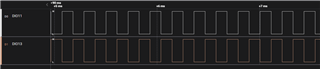
7- Build and run the code
8- Results:
I hope this will help,
Best regards,
Part Number: CC2340R5
Hi,
Here are the steps I recommend to follow to debug the basic_persistent app c (similar steps can be applied for basic_ble_oad_on_chip, basic_ble_oad_off_chip, etc.).
I- Build the image, flash the device and connect the debugger
II- Enable the “Memory Browser” and “Registers” views
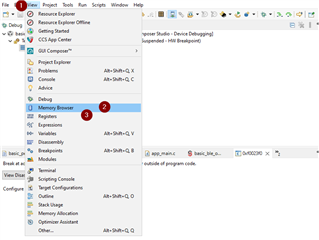
III- Force the device to execute the image you want to debug
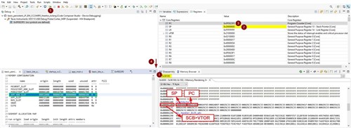
Note: The steps provided here only leads to flash one app (which is the recommended approach for app debugging). In case multiple apps have to be flashed at the same time, Uniflash should be used. Then the step to connect the Debugger to a Running Target described in the Debugger Guide should be followed. And, eventually, the steps in II- and III- should be applied.
Additional suggestions:
- Make sure to review the SImpleLink Connect mobile app (see https://www.ti.com/tool/SIMPLELINK-CONNECT-SW-MOBILE-APP).
- A CC2340R5 flashed with the host_test example and BTool can be used as OAD distributor
I hope this will help!
Part Number: CC2340R5
We have recently released a new debug logging feature on the SimpleLink Low Power F3 SDK for the CC23xx devices. The logging feature allows users to output a debug message into a log within your IDE, similar to UART messages in a serial terminal. This allows for easier debugging capabilities without needing to use a UART peripheral. This post will provide some examples to help with the implementation of this feature.
The Log example is included in the SimpleLink Low Power F3 SDK for the CC23xx. The log example showcases how the log driver works and is a helpful reference for adding the logging functionality to your custom project. This driver implements the functionality necessary to output custom debug messages that can be viewed through Runtime Object Viewer (ROV). The example log project includes a counter that outputs the updated number every five seconds, and two initial "Hello World!" outputs within the main loop to confirm the log is working.
The log feature can be added to any other project in the SDK. To do this, add the log module via SysConfig. These SysConfig log modules can be customized for different purposes, in this example, the default name and settings from the log driver example are used. Within the log SysConfig module, you can customize where the log is sent to, and filter the debug messages that are sent by the log driver.
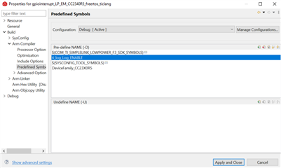
To implement the log feature in any program, start by adding the predefined symbols (ti_log_Log_ENABLE) to enable the logging functionality. The predefined symbols section can be found by right clicking the project, going to Properties->Build->Arm compiler->Predefined Symbols. The image below shows what is to be added.
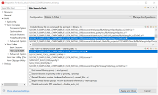
Additionally, an include file needs to be added within the File Search Path.
Default path: ${COM_TI_SIMPLELINK_LOWPOWER_F3_SDK_INSTALL_DIR}/source/ti/log/lib/ticlang/m0p/log_cc23x0r5.a
The File Search Path is accessible by right clicking on the project, going to Properties -> Build -> Arm Linker -> File Search Path. The second image below this will show what needs to be added into the Include library file or command file as input (--library, -l).
Next, the modules within SysConfig need to be setup. Depending on the application, the modules may be setup differently, but for this example, the default module from the log driver example can be used. The picture shows an example setup, including the global parameters section.
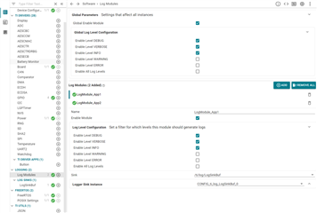
In this image, two modules were created.
The include statements for the log need to be added in the include section of the primary program and the main program for a BLE example. Along with this, the two lines of code below should be added to the main function of the program.
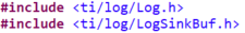
The following two lines of code is how you would send a debug message to LogModule_App1 and LogModule_App2, with a log level of DEBUG.

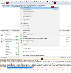
After this, the program needs to be ran in debug mode. To open the log menu, go to Tools -> Runtime Object View. Within ROV, open the LogSinkBuf. Within here two "Hello World!" outputs should be seen.
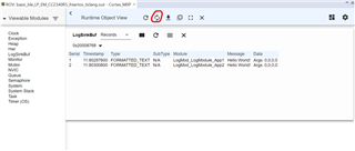
The constant refresh button is circled in the picture above. This feature is useful when receiving messages at a constant rate.
Additional print statements can be added to different functions and interrupts. This allows for easier debugging and output of information. For more information about this feature, please read the log API description found in the TI drivers API guide contained within the BLE5 Stack User's Guide.
Part Number: LP-CC2652R7
Hello All E2E Community Members,
TI has released software support for the Amazon Sidewalk protocol.
The TI Sidewalk Stack is included in SIMPLELINK_CC13XX_CC26XX_SDK version 6.41.00.17 and later.
Support is currently provided for CC2652R7 and CC1352P7-1 LaunchPads.
For more information, please consult the following resources:
Part Number: CC2652R
SysTick can be used to achieve time tracking with 20.833 ns accuracy (i.e. same accuracy as the System Clock).
More details, such as API description can be found here.
The code below can be used to replace the content of empty.c in the empty example.
This code does the following:
/* Driver Header files */
#include <ti/drivers/GPIO.h>

/* RTOS header files */
#include <ti/sysbios/BIOS.h>

/* Driver configuration */
#include "ti_drivers_config.h"

/* For Systick */
#include <ti/devices/DeviceFamily.h>
#include DeviceFamily_constructPath(driverlib/systick.h)
#include DeviceFamily_constructPath(driverlib/interrupt.h)

/*
 *  ======== mainThread ========
 */
/* Systick callback executed every time the timer is wrapped */
void TickTimerISR(void){
    GPIO_toggle(CONFIG_GPIO_LED_0);
}

const int NUM_TS_SAMPLES = 100;
uint32_t tickstamps[NUM_TS_SAMPLES] = {0};

void *mainThread(void *arg0)
{
     int i;

     /* GPIO initialization and configuration */
     GPIO_init();
     GPIO_setConfig(CONFIG_GPIO_LED_0, GPIO_CFG_OUT_STD | GPIO_CFG_OUT_LOW);

     /* Systick  configuration */
     SysTickDisable();
     SysTickPeriodSet(48000000); // 1s interrupt timing ==> TickTimerISR() is executed every 1 second
     SysTickIntRegister(TickTimerISR);
     SysTickIntEnable();
     SysTickEnable();
     IntMasterEnable();


     while(1) {

         /* Random delay */
         volatile int delay = (123456 + 7890123*tickstamps[i]) % 1234567;

         /* Systick collection */
         tickstamps[i++] = SysTickValueGet();

         if(i == NUM_TS_SAMPLES)
         {
             i = 0;
         }
     };
}
Note: The code provided here is applicable to pretty much all the CC26xx and CC13xx devices (including CC2640R2F, CC2651, CC2652R7, CC1311, etc.)
Part Number: CC2651R3
This thread share two ways to evaluate OAD with the LP_CC2651P3 or LP_CC2651R3SIPA. The instructions can also be used with custom designs for a CC2651R3 or CC2651P3 or CC2651R3SIPA. This thread only discuss BLE based OAD.
Option 1: Evaluate OAD using project_zero
In that case, the evaluation can be done similarly to what is done with the LAUNCHXL-CC26X2R1. Just make sure to remember to flash a compatible BIM on the device (i.e. built or pre-built for the device you are using). Additional details can be found here.
Option 2: Enable OAD on the simple_peripheral example
This option consists in following the steps described for the LAUNCHXL-CC26X2R1 in this SimpleLink Academy lab.
Here are a few remarks to help:
To save you some time, you can leverage the files I have obtained when following these steps with simplelink_cc13xx_cc26xx_sdk_6_20_00_29:
I hope this will help,
Best regards,
TI is pleased to announce a new TI Arm Clang Compiler Tools version 2.1.0.LTS which includes the following new features.
New features:
For More Information:
Access:
Part Number: SIMPLELINK-CC13XX-CC26XX-SDK
The project.syscfg(ex: simple_peripheral.syscfg) file expects one more argument in simplelink_cc13xx_cc26xx_sdk_5_30_00_56 SDK.
The argument is to set the rtos version for the project either tirtos or freertos. Without the argument, it will result linker error, missing symbols for kernel objects.
Therefore, when porting from 5.20 SDK to 5.30 SDK, you need to manually update your project.syscfg file from
// @cliArgs --board /ti/boards/CC26X2R1_LAUNCHXL
to
// @cliArgs --board /ti/boards/CC26X2R1_LAUNCHXL --rtos tirtos
Assuming you are using tirtos for your project
