TI Hardware and Software Programming Tools
TI offers several hardware and software solutions for performing both in-system and off board programming TI Connectivity Devices such as those from the CC25XX, CC13xXX & CC26XX device families.
For more information on each of these products, please click on the corresponding link in the tables.
|
Programming Tool |
In System |
Off Board |
Typical Use Case |
|
X |
X |
Mass production in-system and off board programming |
|
|
X |
X |
Mass production in-system and off board programming |
|
|
X |
X |
Debugging, in-system and offboard programming |
|
|
X |
X |
Debugging, in-system and offboard programming |
Connectivity Third Party Programming Solutions
We understand that the programming solutions offered directly from TI may not meet every customer’s needs. Below is a non-comprehensive list of known third parties that support TI Connectivity Devices during various stages of your programming journey.
|
Provider |
Hardware Programming ToolsAvailable |
Software Programming Tools Available |
Production Programming Services Available |
|
X |
|||
|
X |
|||
|
X |
X |
||
|
X |
|||
|
X |
X |
||
|
X |
|||
|
X |
|||
|
X |
X |
||
|
X |
X |
||
|
X |
X |
||
|
X |
X |
||
|
X |
X |
Note: TI does not directly support the following third parties. Any and all engagements or support should be conducted with the party listed directly.
Local distributors also typically offer programming services when buying TI Connectivity devices. Please contact your local distributor for more information.
Part Number: CC2640R2F
Wearable temperature patches are emerging in patient temperature-monitoring systems. One of the biggest hurdles in designing these patches for use in a clinical setting is to meet the stringent accuracy requirements.
The American Society for Testing and Materials (ASTM) specifies electronic patient thermometer accuracy requirements as shown in Table 1. In the most stringent range, these standards allow a maximum error of ±0.1oC to ensure an accurate measurement of a patient’s temperature.
|
Temperature (°C) |
Maximum error (°C) |
|
< 35.8 |
±0.3 |
|
35.8-37.0 |
±0.2 |
|
37.0-39.0 |
±0.1 |
|
39.0-41.0 |
±0.2 |
|
> 41.0 |
±0.3 |
Table 1: Requirements for temperature accuracy under ASTM E1112-00(2016)
Beyond selecting an accurate temperature sensor, achieving true ±0.1°C accuracy in a clinical temperature probe or a wearable temperature patch can be challenging for the following reasons:
In this post, I’ll discuss the block diagram for wearable temperature monitoring systems, and share challenges for thermal designs.
Reference System Block Diagram
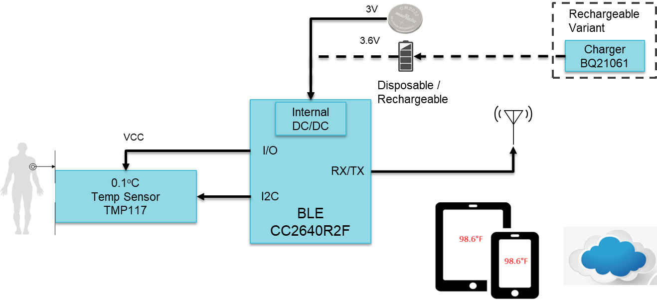
Figure 1: Reference system block diagram for a wearable temperature patch
In many cases, a disposable temperature patch system consists of a coin cell battery, connected MCU and temperature sensor. However, in a rechargeable variant, the system also includes a battery charger as shown in Figure 1. For wearable patches, the battery can be flexible, so the patch can stick properly to the patient’s skin.
One of the key design challenges is to guarantee high measurement accuracy while maintaining a small physical profile for patient comfort. Using highly integrated devices enables a slim temperature patch profile for improving patient comfort. The key devices selected for this system to meet the key requirements are TMP117, CC2640R2F and BQ21061 (for rechargeable variant). Their description is shown below.
The TMP117 is a high-precision digital temperature sensor. It is designed to meet ASTM E1112 and ISO 80601 requirements for electronic patient thermometers. The TMP117 provides a 16-bit temperature result with a resolution of 0.0078°C and an accuracy of up to ±0.1°C across the temperature range of -20°C to 50°C with no calibration.
The SimpleLink™, Bluetooth® Low Energy CC2640R2F is a wireless microcontroller (MCU) targeting Bluetooth 5.1 Low Energy (LE) applications. The low active RF and MCU currents and low-power mode current consumption can provide excellent lifetime for energy-harvesting applications or applications that require small batteries. Available in 4x4, 5x5 and 7x7 QFN packages, the CC2640R2F also integrates a DC/DC converter to simplify battery-powered designs.
The BQ21061 is a highly integrated battery charge management IC that integrates the most common functions for wearable, portable and small medical devices, namely a charger, regulated output voltage rail for system power, LDO and push-button controller. The BQ21061 IC integrates a linear charger with PowerPath that enables quick and accurate charging for small batteries while providing a regulated voltage to the system. The push-button controller can help achieving ship-mode feature for the wearable patches.
Some more important aspects of selecting a sensing element (thermistor or integrated circuit temperature sensor, challenges in designing for minimal temperature like sensor’s thermal contact with patient and isolation from other heat sources etc. are discussed on our blog Design considerations for a wearable temperature monitoring system
Conclusion
Medical accuracy for patient temperature monitors poses some difficult thermal challenges. With the right sensor, you can overcome these difficulties with an understanding of how to take advantage of the placement and layout of your system.
Additional resources
Part Number: CC2640R2F
Tool/software: Code Composer Studio
This solution works for CC26x0 and CC26x2 devices (it includes CC2640R2, CC2642R, CC2652R, CC2652P, CC1312R, CC1352R, CC1352P).
I have tested it using CCS 9.3.
The possibility to connect the debugger to a running target can help you if you want to see the status of your target after several days, or if you cannot reproduce a crash with the debugger attached. Let's dive in it!
1- Modify the GEL file
In a very simplistic view, the GEL files describe the way the device’s debugger has to act (more details can be found in the CCS’s help). By default, the GEL files ask the device to reset when the debugger is started up. Hopefully we can modify this:
a- Identify the GEL files used
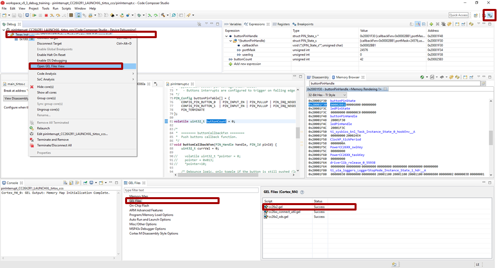
>> Another possibility consists in looking in the <CCS directory>\ccs_base\emulation\gel for the GEL files.
b- In the StartUp() function, comment out the code executing the reset. If needed, an explicit comment will help you to identify the code to comment out.
Here the content of the StartUp() function after modification:
StartUp(int major, int minor, int patch)
{
    /* Initialize memory map */
    memorymap_init();

    /* Debugger specific handling */
    if(GEL_MatchesConnection(".*TIXDS.*") == 1)
    {
        GEL_LoadGel("$(GEL_file_dir)/cc26xx_connect_util.gel");
        GEL_LoadGel("$(GEL_file_dir)/cc26x2_xds.gel");

        DefineResets(0);

        // Issue Board Reset to ensure device is in a known state
        // Note: If you want to attach to a running target without resetting the
        //       device, you must comment out the following 4 lines:
//        if(!GEL_IsConnected())
//        {
//            GEL_AdvancedReset("Board Reset");
//        }
    }
    else if(GEL_MatchesConnection(".*JLink.*") == 1)
    {
        GEL_LoadGel("$(GEL_file_dir)/cc26xx_jlink.gel");
    }
    else
    {
        GEL_TextOut("Error: Unknown debugger.\n");
        return;
    }
}
c- Save you modification and close the file. Stop your debugging session.
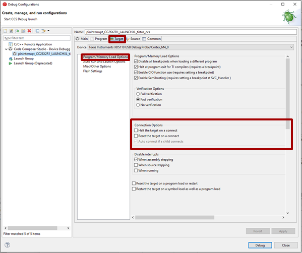
2- Modify the Debug Configuration of your project
Once you have clicked CCS’s debug button (the green bug), CCS is doing a lot of different actions for you. For example CCS loads the program and stops the execution of the code on the target. In our case, we don’t want CCS to load the program (as we already have a running program…). In the same idea, we don’t necessarily want to stop the execution of the code on the target.
Hopefully, the way CCS is running a debug session is highly configurable. So let’s adapt those configurations to our needs.
a- On the right of the Debug button, there is an arrow. Click this arrow and select “Debug Configurations...”.
b- Select your project.
c- Prevent CCS to load the program: in the “Program” tab, chose the proper “Loading option”

d- Prevent CCS to stop the target: in the “Target” tab, deselect the option “Hal the target on a connect”
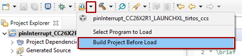
3- [Optional] Prevent CCS to build the program before load.
As no program will be loaded, it is a bit useless to ask CCS to build an image when you start a debug session. As result, you can disable this option by using the small arrow at the right of the Flash button. Click on “Build Project Before Load” in order to disable the option
You are all set now! Let the code running and when needed connect the running target using the Debug button as you usually do.
Q: How can I load a new image on the device now?
A: The easiest way is to use the Flash button and select the image to flash. Don’t forget to rebuild your image manually (as we have disabled the option before). Another solution consists in undoing all the configuration changes we did before. A third solution consists in using a different version of CCS.
Q: Does these configurations affect all my devices?
A: It depends on the modifications
As part of the TI Product Security Incident Response Team (PSIRT) process, this page is to collectively gather any notifications from TI to address vulnerabilities reported to us.
SweynTooth
Reference: https://asset-group.github.io/disclosures/sweyntooth/
Bluetooth Low Energy – unexpected public key crash (SweynTooth)
Bluetooth Low Energy – invalid connection request (SweynTooth)
Others
Bluetooth Low Energy spoofing attack (BLESA)
Release Date: Feb. 28, 2020
As part of the TI Product Security Incident Response Team (PSIRT) process, we would like to notify you about the potential vulnerability of invalid connection request as mentioned part of the SweynTooth vulnerabilities.
The information related to CVE-2019-19193 can be found on www.ti.com/PSIRT under advisory ID TI-PSIRT-2019-100036
Part Number: LAUNCHXL-CC26X2R1
1. [connection-AoA] The peripheral (rtls_slave) cannot answer a CTE request (LL_CTE_REQ PDU) with a LL_CTE_RSP in the same connection event. In other words, the peripheral will send a CTE every second connection-interval.
0. [RTLS_Monitor] We do not release anymore RTLS_Monitor. Instead, we provide a new user interface (UI) stored in your SDK in tools\ble5stack\rtls_agent\rtls_ui. Execute rtls_ui.exe, we advice you to have Google Chrome or Firefox as default web browser.
1. [TOF] Some connection issues have been detected and reproduced while using the new UI. We are currently working on them. For the moment, if you experience this problem, we advice you to restart the GUI and reset the devices.
2. [RTLS_UI] When a connection is dropped by the devices (i.e. not closed using the "Disconnect" button in the GUI), the connection status becomes incorrect. The logs display properly the “Disconnection success” but we still have the “Disconnect” and “Enable …” buttons available. However, you will experience an error if you click on one of those buttons. In this case, we advice you to click "Disconnect" and then reconnect your devices.
3. [AOA] AoA multiple connection: When>4 slaves are connected, the master node might disconnect after aoa_start command is sent. WA requires delaying the aoa_start command for a few seconds after the connection is established.
4. [AOA] AoA multiple connection: When>4 slaves are connected, the passive node sometimes fails to track some of the connections.
5. [AOA] In some cases, the angle measured is stuck at a given value. We are currently working on this problem. For the moment, if you experience this problem, we advice you to restart the GUI and reset the devices. A mass-erase and a re-flash of the devices might also been required.
1. [RTLS Passive] AoA angle calculation is deviated in small angles (0-10 degrees)
2. [RTLS] Angle performance is not stable when antenna array 2 is used
3. [RTLS] Configuration of slot_duration=1 is not supported in AoA
4. [TOF] ToF Master/Slave may go out of sync when RSSI is below -60
[Workaround]: This workaround corrects the issue BLE_AGAMA-1411 (ToF Master/Slave may go out of sync when RSSI is below -60).
In your RTLS project, replace the files TOF.c/.h and tof_security.c/.h by the following ones:
5. TOF is not stable for connection interval greater than 1 second
6. [AOA] When using only two antennas, the following code modifications are required:
#define AOA_NUM_ANTENNAS 2 //3 //!< Number of antennas in antenna array
  uint8_t antArray[AOA_NUM_ANTENNAS + 1] = {ANT2, ANT1, ANT_ARRAY};

  AOA_initAntArray(antArray, AOA_NUM_ANTENNAS + 1);
const int16_t AoA_A1 = antA1Result->pairAngle[0] + antA1Result->channelOffset[antA1Result->ch];
const int16_t signalStrength_A1 = (antA1Result->signalStrength[0]);
7. When only the master and the slave devices are used, the GUI does not display the AOA properly. A workaround has been provided in this thread.
1. rtls_agent_cli has an issue where the incorrect AoA start request can be invoked via the websocket (e.g. when using RTLS_Monitor GUI)
The fix is to remove any references to _cc2640r2 flavors of commands. from ss_rtls.py. See the snippet below on which code should be removed
    class AoaStartReq_cc2640r2(NpiRequest, SyncReq, FromAp):
        command = Commands.RTLS_CMD_AOA_ENABLE
        struct = Struct(
            "enable" / Int8ul,
        )

    class AoaSetParamsReq_cc2640r2(NpiRequest, SyncReq, FromAp):
        command = Commands.RTLS_CMD_AOA_SET_PARAMS
        struct = Struct(
            "aoaRole" / Enum(Int8ul, AoaRole),
            "aoaResultMode" / Enum(Int8ul, AoaResultMode),
            "cteScanOvs" / Int8ul,
            "cteOffset" / Int8ul,
            "cteTime" / Int16ul,
        )
Also the following code should be removed from the bottom of the file:
    @builder_class(AoaStartReq_cc2640r2)
    def aoa_start_cc2640r2(self, enable): pass

    @builder_class(AoaSetParamsReq_cc2640r2)
    def aoa_set_params_cc2640r2(self, aoaRole, aoaResultMode, cteScanOvs, cteOffset, cteTime): pass
2. All the readme.html are missing for rtls examples.
The original README.md files which are used to generate the html files are still in the folder, users can take a look at those files to get started.
3. rtls_master does not support sampling I/Q on AoA pakckets.
For convenience, a new binary can be found here, use this in place of the one in the SDK:
/cfs-file/__key/communityserver-discussions-components-files/538/rtls_5F00_agent_5F00_cli.exe
Part Number: CC2640R2F, CC2642
Please see this thread for Bluetooth Qualification updates.
Customers attempting to create an End-Product listing with our qualified UUIDs, may end up with inconsistencies due to TCRL 2018-1 (Erratum E10734).
For CC2640R2, attached here are test evidence needed to complete the listing;
And here are the test reports:
For CC2640 / CC2650 / CC1350:
These test evidences are based on Category B which means that they were collected by in house testing (Not PTS). Sniffer and logs must be shared with the end-product listing. Here is an example how;
For Peripheral:
|
Test Evidence Information |
||||||
|
Test Case Verdict (Pass, Fail, Waived, Referenced) |
Test Execution (Date) |
Test Equipment Platform |
Test Report Reference |
IUT Configuration |
Integrated QDID |
Evidence Notes |
|
Pass |
28/03/2019 |
CC2640R2F |
BLE5-1.1.3 |
D041506 |
||
For Peripheral+Central:
|
Test Evidence Information |
||||||
|
Test Case Verdict (Pass, Fail, Waived, Referenced) |
Test Execution (Date) |
Test Equipment Platform |
Test Report Reference |
IUT Configuration |
Integrated QDID |
Evidence Notes |
|
Pass |
28/03/2019 |
CC2640R2F |
BLE5-1.1.3 |
D041507 |
||
And here are the test reports:
CC1350:
CC2650:
CC2640R2F (BLE Stack):
CC2640R2F (BLE5 Stack):
For CC26x2/CC13x2, attached here are test evidence needed to complete the BT5.0 listing;
Please consult this thread.
If you are new to the topic and want to learn more on how to qualify your Bluetooth low energy product, please refer to this app note.
This thread has been edited by someone who was not the original author. -Clément
1. There is bug fixed in this SDK where gapbondmgr will now queue the pairing for other connections if there is ongoing pairing.
For more information, please see:EXT_EP-10227
2. When using the Windows installer, there is a chance that the XDCtools component will not install properly. This will cause a build error for IAR examples. If ths has happened, install the XDCTools package directly from: 
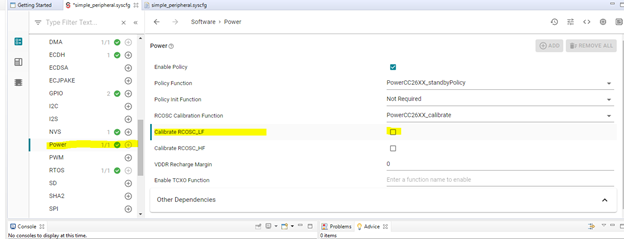
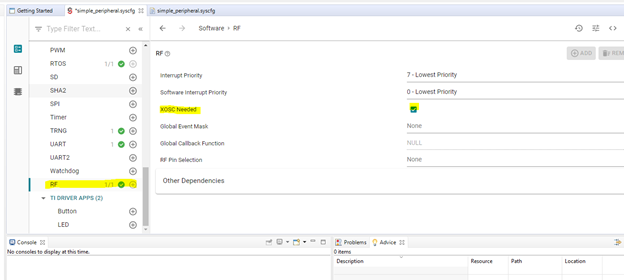
1. [CC26x2RB] When changing the clock configuration from default [RCOSC] to XTAL Clock, the RF settings and the Power settings must be changed too. All those changes can be done in the SysConfi GUI.
Here are some guidelines on how doing those changes:
1. If you try opening SysConfig view in an old version of CCS you will get a build error. Please update to CCS 9.2.0.
2. For IAR users, SysConfig standalone tool is required as a separate installation. Download from here:

3. AE and legacy advertising set number is limited to 20
4. RTOS logging of certain high-priority events, such as SWIs and HWIs, may interfere with reception of a scan response chain
5. CC1352-P2 fails to enable legacy advertise command when channel 37 is not included in the channel map. The work-around is to include channel 37 in the advertising channel map.
6. Example failed to load when configured to non-default power level in the advertisement sets. Make sure not to change the power level in advertisement sets. HCI_EXT_SetTxPowerCmd() can be used to set Tx power at runtime.
7. AoA angle calculation is deviated in small angles (0-10 degrees)
8. Angle performance is not stable when antenna array 2 is used
9. [Multi-Sensor] Accelerometer Service Disappears After First Connection
10. Configuration of slot_duration=1 is not supported in AoA
11. ToF Master/Slave may go out of sync when RSSI is below -60
12. ToF is not stable for connection interval greater than 1 second
13. CC13x2-P2 persistent app failed to compile in debug configuration. Please use Release build configuration.
14. Simple Central: No connection timeout when connection is unsuccessful. To work around this, implement a clock that times out after a given time and resets the device.
15. When using multi-role, there exists an issue where a random address will display instead of the “Work With” selection in the serial terminal.
16. The NVS Driver is now used for bond storage. It is not possible to retain OSAL_SNV contents when upgrading from BLE5 1.1.x releases.
1. AE and legacy advertising set number is limited to 20
2. RTOS logging of certain high-priority events, such as SWIs and HWIs, may interfere with reception of a scan response chain
3. Simple Central: No connection timeout when connection is unsuccessful.
To work around this, implement a clock that times out after a given time and resets the device.
4. When using multi-role, there exists an issue where a random address will display instead of the “Work With” selection in the serial terminal.
5. The NV Driver is now used for SNV record & bond storage. It is not possible to retain OSAL SNV contents when upgrading from earlier BLE5 1.1.x releases. Two flash pages of NV are required.
6. Simple Central can't save Bond data for more than 10 devices to NV.
7. When building the ble5 simple peripheral oad offchip app project without the SECURITY define, there are 4-6 a build errors. To resolve them, add the following #ifdef in oad_util.c:
#ifdef SECURITY
 uint8_t OADUtil_signCommandECDSA(securityHdr_t * secHdr,
                                    signPld_ECDSA_P256_t *signPld,
                                    uint8_t *payload, uint16_t len)
{
...
}
#endif
and in oad_util.h:
#ifdef SECURITY
extern uint8_t OADUtil_signCommandECDSA(securityHdr_t * secHdr,
                                        signPld_ECDSA_P256_t *signPld,
                                        uint8_t *payload, uint16_t len);

#ifdef __cplusplus
}
#endif
#endif
8. Scanning filter policy (SCAN_PARAM_FLT_POLICY) does not work
9. Incoming Slave Security Request not handled properly by the GapBondMgr and will trigger a new pairing process
10. [BTool] When reading "Multiple Characteristic Values" doesn't appear the value at the field as expected
11. [BTool] Secure Connections Bond returns False although the GAP_BondComplete event succeeds
12. [BTool] Create connection with invalid connection param received error but the parameters doesn't return to default
13. [BTool] Discovered devices list is never cleared.
14. [BTool] Peer device switching PHY: from 1M to 2M and then to coded received PHY update complete for 1M, 2M instead of Coded
15. [RTLS] TOF accuracy: For 20 m distance results show above ~30 m
16. [RTLS] TOF is not stable for connection interval greater than 1 second.
17. [RTLS] rtls_passive won't re-sync when using TOF_MODE_AUTO run mode in Dynamic Sync-word mode
18. When using the Watchdog, the TI ROV will display an Uninitialized Task Object. This is expected. Please see https://e2e.ti.com/support/processors/f/791/p/827739/3061540.
1. Known issue where queued param updates in slave device makes device crash
In SimplePeripheral_processParamUpdate(), the param update data and clock should only be freed / destructed when the status of the update is bleAlreadyInRequestedMode. Therefore, this freeing / destructing should be surround by a check for this status:
// Send parameter update
bStatus_t status = GAP_UpdateLinkParamReq(&req);
// If there is an ongoing update, queue this for when the udpate completes
if (status == bleAlreadyInRequestedMode)
{
spConnHandleEntry_t *connHandleEntry = ICall_malloc(sizeof(spConnHandleEntry_t));
if (connHandleEntry)
{
connHandleEntry->connHandle = connHandle;
List_put(¶mUpdateList, (List_Elem *)connHandleEntry);
}
}
else
{
// Deconstruct the clock object
Clock_destruct(connList[connIndex].pUpdateClock);
// Free clock struct
ICall_free(connList[connIndex].pUpdateClock);
connList[connIndex].pUpdateClock = NULL;
// Free ParamUpdateEventData
ICall_free(connList[connIndex].pParamUpdateEventData);
}
2. AE and legacy advertising set number is limited to 20
3. RTOS logging of certain high-priority events, such as SWIs and HWIs, may interfere with reception of a scan response chain
4. Simple Peripheral Application freezes when selecting “Work With” when connected to 3 or more central devices
5. Simple Central: No connection timeout when connection is unsuccessful.
To work around this, implement a clock that times out after a given time and resets the device.
6. When using multi-role, there exists an issue where a random address will display instead of the “Work With” selection in the serial terminal.
7. The NV Driver is now used for SNV record & bond storage. It is not possible to retain OSAL SNV contents when upgrading from earlier BLE5 1.1.x releases. Two flash pages of NV are required.
8. [SysConfig]Scan Duration displays wrong range
9. Simple Central can't save Bond data for more than 10 devices to NV.
10. When one device is walking out of range, one or more of the other connections may also be dropped.
11.[SysConfig]Scan Duration displays wrong range
12. [SysConfig]CC13x2 devices Two Buttom Menu does not work. Work-around presented below:
In CCS:
Open Project -> Properties -> Build -> ARM Compiler -> Predefined Symbols. Add in the Pre-define section one of the following, according to the device in use: CC13X2P1_LAUNCHXL/CC13X2R1_LAUNCHXL/CC13X2P_2_LAUNCHXL/ CC13X2P_4_LAUNCHXL. Press Apply and Close.
In IAR:
Open Project -> Options -> C/C++ Compiler -> Preprocessor. Add to Defined symbols section one of the following, according to the device in use: CC13X2P1_LAUNCHXL/CC13X2R1_LAUNCHXL/CC13X2P_2_LAUNCHXL/ CC13X2P_4_LAUNCHXL. Press OK.
13. [BTool] When reading "Multiple Characteristic Values" doesn't appear the value at the field as expected
14. [BTool] Secure Connections Bond returns False although the GAP_BondComplete event succeeds
15. [BTool] Create connection with invalid connection param received error but the parameters doesn't return to default
16. [BTool] The application always starts as Central configuration even if loads host_test_peripheral.hex
17. [BTool] Discovered devices list is never cleared.
18. [BTool] Peer device switching PHY: from 1M to 2M and then to coded received PHY update complete for 1M, 2M instead of Coded
19. When using GAP_ADV_ENABLE_OPTIONS_USE_DURATION option for advertising, there has been problems observed such as device terminated when the advertising duration ends. The current workaround is to use a software timer to stop advertising instead of using GAP_ADV_ENABLE_OPTIONS_USE_DURATION option.
20. When building the ble5 simple peripheral oad offchip app project without the SECURITY define, there are 4-6 a build errors. To resolve them, add the following #ifdef in oad_util.c:
#ifdef SECURITY
 uint8_t OADUtil_signCommandECDSA(securityHdr_t * secHdr,
                                    signPld_ECDSA_P256_t *signPld,
                                    uint8_t *payload, uint16_t len)
{
...
}
#endif
and in oad_util.h:
#ifdef SECURITY
extern uint8_t OADUtil_signCommandECDSA(securityHdr_t * secHdr,
                                        signPld_ECDSA_P256_t *signPld,
                                        uint8_t *payload, uint16_t len);

#ifdef __cplusplus
}
#endif
#endif
simplelink_cc13x2_26x2_sdk_2_40_00_81
1. Known issue where queued param updates in slave device cause application assert
2. When using GAP_ADV_ENABLE_OPTIONS_USE_DURATION option for advertising, there has been problems observed such as device terminated when the advertising duration ends. The current workaround is to use a software timer to stop advertising instead of using GAP_ADV_ENABLE_OPTIONS_USE_DURATION option.
3. Can not disable adv set 0 when connected on LE Coded PHY. When simple peripheral is connected on LE Coded PHY and has reached it's maximum number of connections, trying to disable the LE 1M PHY advertising set fails with the error code bleInternalError and the device continues advertising.
4.BLE hex files missing
There has been restructure of the software packaging, therefore the hex files are moved to the following folder C:\ti\simplelink_cc13x2_26x2_sdk_2_40_00_81\source\ti\ble5stack\hexfiles
This will be fixed in the newer SDK.
1.Simple Peripheral: appears Bond save success on simple_peripheral side after enter wrong passkey on master during pairing/bonding.
This is fixed fin later releases. To fix add this if-clause around the gap bond callback in gapbondmgr.c:
        if((pPkt->hdr.status == SUCCESS) &&
           (pPkt->authState & SM_AUTH_STATE_BONDING))
        {
          // Report to app
          pGapBondCB->pairStateCB( pPkt->connectionHandle,
                                   GAPBOND_PAIRING_STATE_BOND_SAVED,
                                   saveStatus );
}1: How do I enable the TI-RTOS Object Viewer (ROV) in IAR?
A: The ROV can be enabled under the application's Project Options -> Debugger -> Plugins tab. Select "TI-RTOS" in the scroll list.
2: Why does my CC2650STK SensorTag only work when I debug in CCS?
A: The SensorTag requires the use of a Boot Image Manager (BIM) which needs to be programmed in addition to the App & Stack projects. The BIM is included in the prebuilt firmware hex image. Refer to the Firmware Build Procedure in the SensorTag User Guide on the TI BLE Wiki.
3: My "out-of-the-box" BLE examples does not compile in IAR and I get an error saying "Variable expansion failed". What is wrong?
A: IAR sometimes fail to include the path variables for TI RTOS and CC26XXWARE and you need to import them again manually.
Go to Project->Configure Custom Argument Variables, Select Import and choose the corresponding variables file. Example location: Projects\ble\SimpleBLEPeripheral\CC26xx\IAR\SimpleBlePeripheral.custom_argvars
4: I encounter a pre-build error indicating that lib_search.exe is not recognized in BLE-Stack v3.0 / CC2640R2 SDK v1.0.0.22
A: The lib_search.exe executable used during the Stack pre-build steap in this SDK requires a Windows 64-bit installation. For 32-bit Windows installations, please use this 32-bit version of lib_search.exe (zip). Starting with CC2640R2 SDK v1.30.00.25 a 32-bit compatible version is provided.
5: My CC-DEVPACK-DEBUGGER (DevPack Debugger / XDS110) does not detect the SensorTag in SmartRF Flash Programmer 2 v1.7.x+?
A: A firmware update may be required. Please install CCS according to the CC2640 BLE Software Developer’s Guide (SWRU393). CCS will detect if a firmware update is required when a Debug session is started. Open and build the SensorTag project, then program the SensorTag via the CCS Debugger. Remember to close SmartRF Flash Programmer 2.
6: I’m getting a linker or post-build error with Boundary.exe when building the Stack project.
A: (Applies to BLE-Stack v2.1.1 and earlier SDK releases) The Boundary tool is used to adjust the Stack flash / RAM boundary to the optimal value. These errors typically occur when the Stack configuration is modified such that RAM/Flash usage has changed.
For BLE-Stack v2.2.0+: the Frontier tool is used and a rebuild of the Stack project is not required. Details are provided in the CC2640 BLE Software Developer’s Guide, but the process is to build the Stack, then build the App. A rebuild of the Stack is only required if changing the Stack project.
7: I get pre-build errors in IAR, and after clicking Tools->Options->Messages->Show all build messages, it looks something like this
gmake[1]: Entering directory `C:/ti/simplelink/ble_cc26xx_2_00_00_42893/Projects/ble/SimpleBLEPeripheral/CC26xx/IAR/Config/src/sysbios'
Preprocessing library source files ...
C:/Users/<user>/AppData/Local/Temp/make904-2.sh: 1: Syntax error: "(" unexpected
C:/Users/<user>/AppData/Local/Temp/make904-3.sh: 1: Syntax error: "(" unexpected
A: Your system has for whatever reason disabled 8.3 pathname aliases (e.g. PROGRA~2) for the path IAR is installed to. The only known working solution is currently to install IAR at e.g. C:\IAR\EWARM7401 or some other path without spaces or long names.
8: I get "Resource temporarily unavailable" pre-build errors in the application project similar to this:
Creating the SYS/BIOS library that contains the APIs not included in the ROM ...
0 [main] sh 6420 sync_with_child: child 6332(0x19C) died before initialization with status code 0xC0000142
23 [main] sh 6420 sync_with_child: *** child state waiting for longjmp
C:/Users/username/AppData/Local/Temp/make6628-1.sh: fork: Resource temporarily unavailable
A: Most likely there is a conflict with sh.exe in the XDCTools installation with some other package you have installed. Please search for sh.exe in your system and disable the conflicting package(s). Additionally, file system tools, such as cygwin may cause conflicts with the XDCTools; these installation(s) should be disabled as well.
9: My CCS project fails to build.
A: First verify you are using the required minimum CCS IDE version and TI Compiler version specified in the Release Notes for the respective SDK. Also, do not use a space in the BLE-Stack SDK path and your CCS workspace or Windows %APPDATA% path. Using a white space in these paths will result in a build error. It is also advisable to install the SDK to the default location to confirm your setup is working correctly. In addition, the pre-build steps may fail if there is a version of Cygwin in your Windows PATH before XDCTools. It is recommended to adjust your PATH such that no other versions of Cygwin are found before XDCTools.
10: I’m still getting build errors of some kind.
A: Please use the E2E "Insert Code, Attach Files and more" option and attach your IAR or CCS build log (paperclip icon). Note that for IAR, you must enable the build log: Tools -> Options -> Messages -> Log build messages to file. Please compress the file as needed. Attaching the build file, and not just the snippet showing the error, is critical to determine the build environment and other factors needed to diagnose your build error.
11: When debugging or loading the Stack FlashROM project, I get errors saying the vector table can’t be found or can’t run to main.
A: The Stack project is not an executable, thus it can’t be debugged directly from the IDE. The Stack must be debugged from the Application project workspace. In IAR, you should not encounter these warnings if “Download Active Application” is used to download (program) the Stack image. In CCS, you will see these warnings, however they can be ignored so long as the flash memory was successfully programmed. After the Stack is downloaded, switch to the Application workspace/project and start the debug session. More details are in the CC2640 BLE Software Developer’s Guide (SWRU393).
12: My CC-DEVPACK-DEBUG (DevPack Debugger / XDS110) always reports "Firmware Upgrade Mode" in the Windows Device Manager?
A: Please make sure you have a battery inserted in the SensorTag and follow the procedure on the wiki: processors.wiki.ti.com/.../CC13xx_CC26xx_Tools_Overview
13: How do I unbrick the device?
A: Use SmartRF Flash Programmer 2. Under the wrench icon (top right), select “CC26xx/CC13xx Forced Mass Erase”. Note that the flash programming tool will always report "success" when performing a mass erase. If the CC26xx Device Configuration (CCFG) has been set to disable the Mass Erase function, the operation will not succeed despite the flash programming tool reporting "success".
14. When debugging or loading the Stack FlashROM project, I get errors saying the vector table can’t be found or can’t run to main.
A: The Stack project is not an executable, thus it can’t be debugged directly from the IDE. The Stack must be debugged from the Application project workspace. In IAR, you should not encounter these warnings if “Download Active Application” is used to download (program) the Stack image. In CCS, you will see these warnings, however they can be ignored so long as the flash memory was successfully programmed. After the Stack is downloaded, switch to the Application workspace/project and start the debug session. More details are in the CC2640 BLE Software Developer’s Guide (SWRU393).
15. How can I run projects using ti-clang compiler with CCS 10.2?
A: Please see this post.
1. CCS cannot find target config file for simple_peripheral_cc2650em_app project.
A: To fix this, open your project properties and select "General". Check the box marked "Manage the project's target-configuration automatically" and change "Connection" to Texas Instruments XDS100V3 USB Debug.
2. Host Test does not automatically respond to Connection Parameter Update Requests and instead allows the application to specify the response parameters. Responses must manually sent within 40 seconds of reception of the GAP_LinkParamUpdateRequest event 0x0612 using HCI_LERemoteConnectionParameterRequestReply or HCI_LERemoteConnectionParameterRequestNegativeReply.
3. Advertising (ADV) may stop when performing extended periods.(more than 1 hour)
A: The workaround is to stop and restart ADV on a periodic basis using a TI-RTOS Clock instance. The reason is due to an anomaly in the TI-RTOS RF Driver used by BLE-Stack v2.2.0 and v2.2.1
4. The CC2650 Remote Control (CC2650RC) "hid_adv_remote_cc2650rc_app" application project in CCS will fail to link due to incorrect TI-RTOS project configuration.
A: To fix this, open your project properties, General -> RTSC tab, select 2.20.1.08 under "TI-RTOS for CC13XX and CC26XX". Rebuild the project.
1. Advertising (ADV) may stop when performing extended periods.(more than 1 hour)
A: The workaround is to stop and restart ADV on a periodic basis using a TI-RTOS Clock instance. The reason is due to an anomaly in the TI-RTOS RF Driver used by BLE-Stack v2.2.0 and v2.2.1
2. SensorTag Application project fails to build on CCS when the project is copied to the Workspace.
A: Do not copy the project to the Workspace when importing the project
3. SNV data may be lost following reset after first time power up when using OSAL_SNV=1 (default setting for stack projects).
A: To apply the fix, edit ble_sdk_2_02_00_31\src\components\services\src\nv\cc26xx\nvocop.c file. See here
const uint8 NV_FLASH[FLASH_PAGE_SIZE] = {0xFF};
4. Potential memory leak caused by using non-atomic Queue APIs that are not thread-safe in util.c.
A : edit ble_sdk_2_02_00_31\src\common\cc26xx\util.c. You can find the detail here
1: When switching to the 5x5 package, UART crashes in my BLE-Stack v2.1.x project, such as when initializing NPI.
A: An issue exists in the TI-RTOS 2.13 CC2650EM_5XD board file with the placement of the uartCC26XXHWAttrs structure. Please make the following change in the 5XD board file, usually located at C:\ti\tirtos_simplelink_2_13_00_06\packages\ti\boards\SRF06EB\CC2650EM_5XD:
#pragma DATA_SECTION(uartCC26XXObjects, ".const:uartCC26XXObjects")
with:
#pragma DATA_SECTION(uartCC26XXHWAttrs, ".const:uartCC26XXHWAttrs")
This issue has been corrected in subsequent TI-RTOS SDK releases for CC26xx and is fully fixed in the BLE-Stack v2.2 SDK.
1. When switching to the 5x5 package, UART crashes in my BLE-Stack v2.1.x project, such as when initializing NPI.
A: An issue exists in the TI-RTOS 2.13 CC2650EM_5XD board file with the placement of the uartCC26XXHWAttrs structure. Please make the following change in the 5XD board file, usually located at C:\ti\tirtos_simplelink_2_13_00_06\packages\ti\boards\SRF06EB\CC2650EM_5XD:
#pragma DATA_SECTION(uartCC26XXObjects, ".const:uartCC26XXObjects")
with:
#pragma DATA_SECTION(uartCC26XXHWAttrs, ".const:uartCC26XXHWAttrs")
This issue has been corrected in subsequent TI-RTOS SDK releases for CC26xx and is fully fixed in the BLE-Stack v2.2 SDK.
